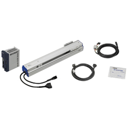
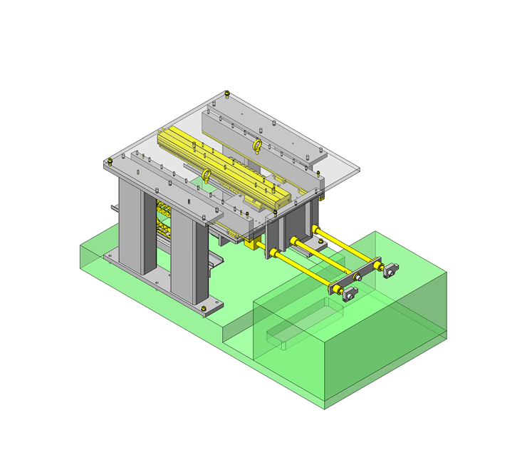
Single Axis Robot
* Orange colored cells in the table below indicate the part numbers used in this example.
Selection criteria
Based on stroke, accuracy and thrust force.
Back to page top
Available sizes
■Single Axis Robot RSH1
Height (mm) | Type | Lead (mm) | Stroke (50mm Increments) |
65 | RSH1 | 6 | 150-800 |
12 |
20 |
RSH2 | 5 | 150-1050 |
10 |
20 |
30 |
RSH3 | 5 | 150-1050 |
10 |
20 |
Back to page top
Selection steps
■Single Axis Robot Selection Steps
Load Capacity
↓
Stroke
↓
Cycle Time or Max. Speed
↓
Check for Details
Back to page top
Accuracy Info.
Single Axis Robot Accuracy
Height (mm) | Type | Lead (mm) | Stroke (50mm Increments) | Positioning Repeatability (mm) |
65 | RSH1 | 6 | 150-800 | ±0.02 |
12 |
20 |
RSH2 | 5 | 150-1050 | ±0.01 |
10 |
20 |
30 |
RSH3 | 5 | 150-1050 | ±0.01 |
10 |
20 |
Back to page top
Performance info.
■Speeds / Loads (Load info.) of Single Axis Robot
Type | Lead (mm) | Max. Load Capacity (kg) | Allowable Moment (N・m) | Max. Velocity (mm/sec) |
Horizontal | Vertical | Pitching | Yawing | Rolling | 150- 550st | 600 st | 650 st | 700 st | 750 st | 800 st |
RSH1 | 6 | 40 | 8 | 95 | 70 | 110 | 360 | 324 | 270 | 234 | 216 | 180 |
12 | 20 | 4 | 720 | 648 | 540 | 468 | 432 | 360 |
20 | 12 | - | 1200 | 1080 | 900 | 780 | 720 | 600 |
Type | Lead (mm) | Max. Load Capacity (kg) | Allowable Moment (N・m) | Max. Velocity (mm/sec) |
Horizontal | Vertical | Pitching | Yawing | Rolling | 150- 650st | 700 st | 750 st | 800 st | 850 st | 900 st | 950 st | 1000 st | 1050 st |
RSH2 | 5 | 50 | 16 | 95 | 70 | 110 | 300 | 255 | 225 | 195 | 180 | 165 | 150 | 135 | 120 |
10 | 40 | 8 | 600 | 510 | 450 | 390 | 360 | 330 | 300 | 270 | 240 |
20 | 20 | 4 | 1200 | 1020 | 900 | 780 | 720 | 660 | 600 | 540 | 480 |
30 | 7 | - | 1800 | 1530 | 1350 | 1170 | 1080 | 990 | 900 | 810 | 720 |
Type | Lead (mm) | Max. Load Capacity (kg) | Allowable Moment (N・m) | Max. Velocity (mm/sec) |
Horizontal | Pitching | Yawing | Rolling | 150- 600st | 650 st | 700 st | 750 st | 800 st | 850 st | 900 st | 950 st | 1000 st | 1050 st |
RSH3 | 5 | 80 | 163 | 128 | 143 | 300 | 255 | 225 | 195 | 180 | 165 | 150 | 135 | 120 | 105 |
10 | 60 | 600 | 510 | 450 | 390 | 360 | 330 | 300 | 270 | 240 | 210 |
20 | 30 | 1200 | 1020 | 900 | 780 | 720 | 660 | 600 | 540 | 480 | 420 |
Back to page top
Technical Calculations
■Technical Calculation for Single Axis Robot
Selection Method of Single Axis Robot
https://sg.misumi-ec.com/maker/misumi/mech/product/rs/
Back to page top
Linear Shafts
* Orange colored cells in the table below indicate the part numbers used in this example.
Selection criteria
Based on accuracy, stroke and design
Back to page top
Available sizes
■Precision Hollow Linear Shafts - Straight
Material | Hardness | Surface Treatment |
52100 Bearing Steel | Induction Hardened 52100 Bearing Steel: 58HRC or More 440C Stainless Steel: 56HRC or More | - |
440C Stainless Steel |
52100 Bearing Steel | Hard Chrome Plating: Plating Hardness HV750 - Plating Thickness 5 µm or more |
52100 Bearing Steel | Low Temp. Black Chrome Plating |
■Sizes and Dimensions
O.D. | Length in 1 mm Increments | Thread Dia. |
3 | 4 | 5 | 6 | 8 | 10 | 12 | 16 | 20 | 24 | 30 | Rc1/8 | Rc1/4 | Rc3/8 |
6 | 20~600 | ○ | - | - | - | - | - | - | - | - | - | - | - | - | - |
8 | 20~800 | - | ○ | ○ | - | - | - | - | - | - | - | - | - | - | - |
10 | 20~800 | - | - | ○ | ○ | - | - | - | - | - | - | - | - | - | - |
12 | 20~1000 | - | - | - | - | ○ | - | - | - | - | - | - | ○ | - | - |
13 | 25~1000 | - | - | - | - | - | ○ | - | - | - | - | - | ○ | - | - |
16 | 30~1200 | - | - | - | - | - | - | ○ | - | - | - | - | - | ○ | - |
20 | 30~1200 | - | - | - | - | - | - | - | ○ | - | - | - | - | - | ○ |
25 | 35~1200 | - | - | - | - | - | - | - | - | ○ | - | - | - | - | - |
30 | 35~1500 | - | - | - | - | - | - | - | - | ○ | - | - | - | - | - |
35 | 35~1500 | - | - | - | - | - | - | - | - | - | ○ | - | - | - | - |
40 | 50~1500 | - | - | - | - | - | - | - | - | - | ○ | ○ | - | - | - |
50 | 60~1500 | - | - | - | - | - | - | - | - | - | - | ○ | - | - | - |
Back to page top
Accuracy Info.
■Accuracy of the Shafts
O.D. (mm) | O.D. Tolerance (mm) g6 |
6 | -0.004 -0.012 |
8 | -0.005 -0.014 |
10 |
12 | -0.006 -0.017 |
13 |
15 |
16 |
18 |
20 | -0.007 -0.020 |
25 |
30 |
35 | -0.009 -0.025 |
40 |
50 |
Back to page top
Oil Free Bushing Housing Unit
Product name | Oil Free Bushing with Housing Units |
Part number | JFBA16 |
Features | Suitable for horizontal use. Reduces the time of manufacturing and assembling the housing. |
* Orange colored cells in the table below indicate the part numbers used in this example.
Selection criteria
Housing unit that supports both linear and rotary motion.
Back to page top
Available sizes
■Oil Free Bushing with Housing Units
Housing | Bushing |
Material | Surface Treatment | Material |
Aluminum Alloy | Clear Anodize | Polyacetal |
■Sizes and Dimensions
I.D. | Mounting Surface - Shaft Bore Dimension | Width | Height |
6 | 14 | 16 | 22 |
8 | 16 | 20 | 26 |
10 | 19 | 26 | 32 |
12 | 20 | 26 | 34 |
16 | 27 | 36 | 49 |
Back to page top
Accuracy Info.
■Accuracy of oil free Bushing
I.D.(mm) | Tolerance |
6 | +0.095 +0.045 |
8 |
10 |
12 | +0.120 +0.060 |
15 |
16 |
Back to page top
IDEA NOTE Combining linear and rotary motion units
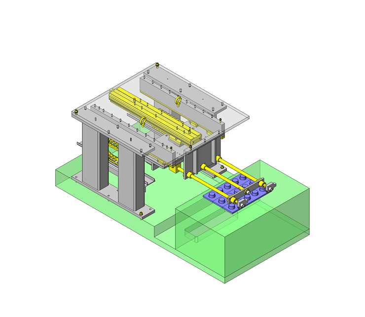
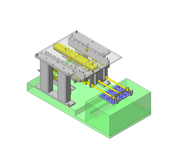
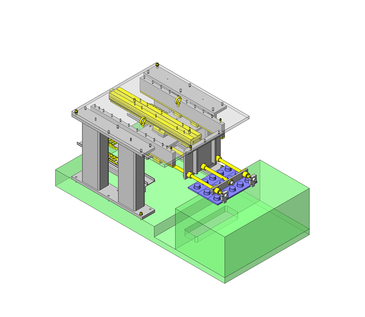
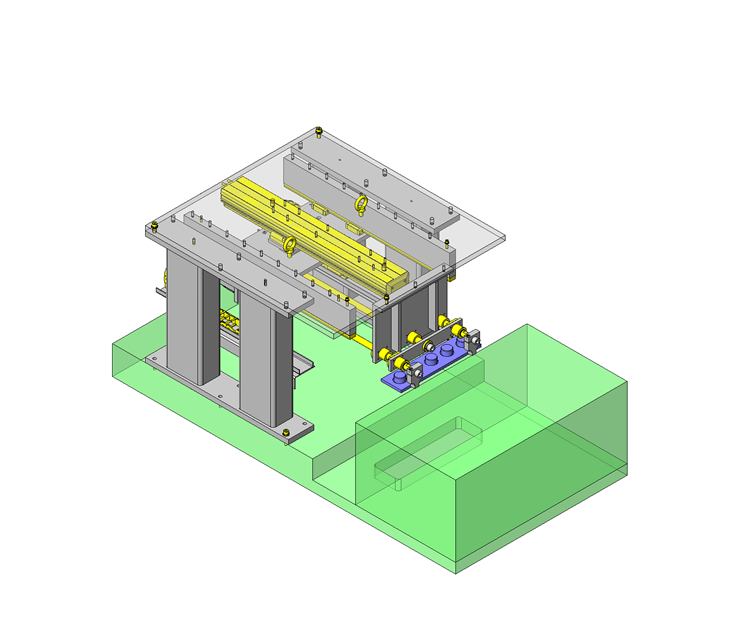
By combining a rotary actuator with a linear actuator, the arm is able to extend and the fingers can rotate.