(!)Due to Microsoft's end of support for Internet Explorer 11 on 15/06/2022, this site does not support the recommended environment.
Instead, please kindly use other browsers like Google Chrome, Microsoft Edge or Mozilla Firefox.
50,000 Stock items for Same Day Ship Out.
All Categories
Categories
- Automation Components
A wide variety of standard and configurable components for factory automation engineers in industries such as automotive, semiconductor, packaging, medical and many more.
- Linear Motion
- Rotary Motion
- Connecting Parts
- Rotary Power Transmission
- Motors
- Conveyors & Material Handling
- Locating, Positioning, Jigs & Fixtures
- Inspection
- Sensors, Switches
- Pneumatics, Hydraulics
- Vacuum Components
- Hydraulic Equipment
- Discharging / Painting Devices
- Pipe, Tubes, Hoses & Fittings
- Modules, Units
- Heaters, Temperature Control
- Framing & Support
- Casters, Leveling Mounts, Posts
- Doors, Cabinet Hardware
- Springs, Shock Absorbers
- Adjusting, Fastening, Magnets
- Antivibration, Soundproofing Materials, Safety Products
- Fasteners
A good selection of accessories such as screws, bolts, washers and nuts that you may need for your daily engineering usage.
- Materials
Browse industrial materials ranging from heat insulating plates, sponges, to metal and plastic materials in different sizes to meet your various applications.
- Wiring Components
A wide variety of wiring parts for connecting and protecting control and PC parts including Connectors, Cables, Electric Wires, Crimping Terminals and more.
- LAN Cables / Industrial Network Cables
- Cables by Application
- Cables with Connectors
- RS232 / Personal Computers / AV Cables
- Wires/Cables
- Connectors (General Purpose)
- Crimp Terminals
- Zip Ties
- Cable Glands
- Cable Bushings/Clips/Stickers
- Screws/Spacers
- Cable Accessories
- Tubes
- Protection Tubes
- Ducts/Wiremolds
- General Purpose Tools
- Dedicated Tools
- Soldering Supplies
- Electrical & Controls
A wide variety of controls and PC parts for electrical engineers including Controls, Powers, PC parts and more.
- Cutting Tools
A wide variety of cutting tools for many uses and work materials including End Mills, Drills, Cutters, Reamers, Turning Tools and more.
- Carbide End Mills
- HSS End Mills
- Milling Cutter Inserts/Holders
- Customized Straight Blade End Mills
- Dedicated Cutters
- Turning Tools
- Drill Bits
- Screw-Hole-Related Tools
- Reamers
- Chamfering / Centering Tools
- Fixtures Related to Cutting Tools
- Step Drills
- Hole Saws
- Clean Key Cutters
- Core Drills (Tip Tools)
- Magnetic Drilling Machine Cutters
- Drill Bits for Electric Drilling Machines
- Woodworking Drill Cutters
- Drills for Concrete
- Processing Tools
A wide variety of tools and supplies used in processing including Machine Tools, Measurement Tools, Grinding and Polishing Supplies and more.
- Material Handling & Storage
A wide variety of goods used in shipment, material handling and warehouse including Tape supplies, Stretch film, Truck, Shelf, Crane and more.
- Tape Supplies
- Cushioning Materials
- Stretch Films
- Cardboard
- Plastic Bags
- PP Bands
- Magic Tapes / Tying Belts
- Rubber Bands
- Strings/Ropes
- Cable Ties
- Tags
- Labelers
- Unpacking Cutters
- Packing Support Equipment
- Cloth Sheets for Packing
- Conveyance/Dolly Carts
- Tool Wagons
- Tool Cabinets / Container Racks
- Lifters / Hand Pallets
- Container Pallets
- Storage Supplies
- Shelves/Racks
- Work Benches
- Suspended Clamps/Suspended Belts
- Jack Winches
- Chain Block Cranes
- Bottles/Containers
- Bicycle Storage Area
- Safety & General Supplies
A large variety of goods for every kind of factories and offices including Protection items, Cleaning supplies, sanitations, office supplies and more.
- Lab & Clean Room Supplies
A large variety of items used in R&D and Clean Room including research Equipment, Laboratory Essentials, Analysis Supplies, Clean Environment-Related Equipment and more.
- Press Die Components
Choose from thousands of standard stamping die components including Punch & Die, Gas Springs, Guide Components, Coil Springs and many more.
- Plastic Mold Components
Browse our wide variety of mold components including Ejector Pins, Sleeves, Leader Components, Sprue Bushings and many more.
- Ejector Pins
- Sleeves, Center Pins
- Core Pins
- Sprue bushings, Gates, and other components
- Date Mark Inserts, Recycle Mark Inserts, Pins with Gas Vent
- Undercut, Plates
- Leader Components, Components for Ejector Space
- Mold Opening Controllers
- Cooling or Heating Components
- Accessories, Others
- Components of Large Mold, Die Casting
- Injection Molding Components
Browse our injection molding components including Heating Items, Couplers, Hoses and more.
- Injection Molding Machine Products
- Accessories of Equipment
- Auxiliary Equipment
- Air Nippers
- Air Cylinders
- Air Chuck for Runner
- Chuck Board Components
- Frames
- Suction Components
- Parallel Air Chuck
- Special Air Chuck
- Chemical for Injection Molding
- Mold Maintenance
- Heating Items
- Heat Insulation Sheets
- Couplers, Plugs, One-touch Joints
- Tubes, Hoses, Peripheral Components
Search by Application
Brands


- Please be informed that our office is closed during the upcoming Labour Day Holiday in 2024. We would also like to inform you that there may be a potential delay in response/shipment from the supplier due to the Japan Golden Week holiday which falls from 29th April to 6th May 2024. Click here for details.
- Please Note our New Address (effective April 1, 2024): 331 North Bridge Rd, #05-01 Odeon 331, Singapore 188720.
CU Series Free Mount Cylinder With Air Cushion (CDU20-20A-M9BW)

Air cylinder that adopts a new air cushion mechanism.
[Features]
· Multiple-surface direct mounting with a square body and no brackets lets you freely choose the mounting surface.
· This enables space-saving designs for equipment.
· Slightly extended dimensions relative to the CU standard models.
· There is no protrusion of the cushion valve, and the width is the same.
· 3 types of mounting orientations can be accommodated according to the installation conditions.
· Approximately 2.4 times more allowable kinetic energy.
· Improved sound insulation (reduced impact of noise at the stroke end).
· Interchangeable mounting.
(i)Caution
- ■ SMC Product Line
Webpages for products currently without individual pages on this site will be released on an ad-hoc basis. - Refer to the manufacturer's catalog for specification and material details.
- Product images may be representative images. Refer to the manufacturer's catalog for shape details.
Part Number
Configured Part Number is shown.
CDU20-20A-M9BW
CU Series Free Mount Cylinder With Air Cushion
| Model | Pneumatic (non-lube) type |
|---|---|
| Fluid | Air |
| Proof Pressure | 1.0 MPa |
| Maximum operating pressure | 0.7 MPa |
| Minimum operating pressure | 0.08 MPa |
| Ambient and Fluid Temperature | Without auto switch: -10°C to +70 ℃ (no freezing) |
| With auto switch: -10°C to +60 ℃ (no freezing) | |
| Rod-end thread | Male thread |
| Stroke Length Tolerance | 0 to +1.0 |
| Operating piston speed | 50 to 500 mm/s |
Effective Cushion Length
- Bore size 20 mm: effective cushion length 6.6 mm
- Bore size 25 mm: effective cushion length 6.7 mm
- Bore size 32 mm: effective cushion length 7.7 mm
Standard Stroke Table
Bore size 20 mm, 25 mm, 32 mm: standard stroke 20 mm, 30 mm, 40 mm, 50 mm, 60 mm, 70 mm, 80 mm, 90 mm, 100 mm
Diagram
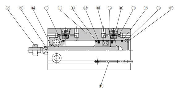
Diagram: CU Series
| Number | Part Name | Material | Quantity | Notes |
|---|---|---|---|---|
| 1 | Cylinder Tube | Aluminum alloy | 1 | Hard anodized aluminum |
| 2 | Rod cover | Aluminum alloy | 1 | Hard anodized aluminum |
| 3 | Head cover | Aluminum alloy | 1 | Chromate |
| 4 | Piston | Aluminum alloy | 1 | Chromate |
| 5 | Piston rod | Stainless steel | 1 | - |
| 6 | Retaining Ring | Carbon tool steel | 1 | Phosphate conversion coating |
| 7 | Rod end nut | Carbon steel | 1 | Chromate |
| 8 | Cushion needle assembly | - | (2) | - |
| 9 | Steel ball | Carbon steel | 2 | - |
| 10 | Magnet | - | 1 | - |
| 11 | Auto switch | - | (2) | - |
| 12 | Piston gasket | NBR | 1 | - |
| 13 | Piston packing | NBR | 2 | - |
| 14 | Rod packing | NBR | 1 | - |
| 15 | Gasket | NBR | 1 | - |
Drawing
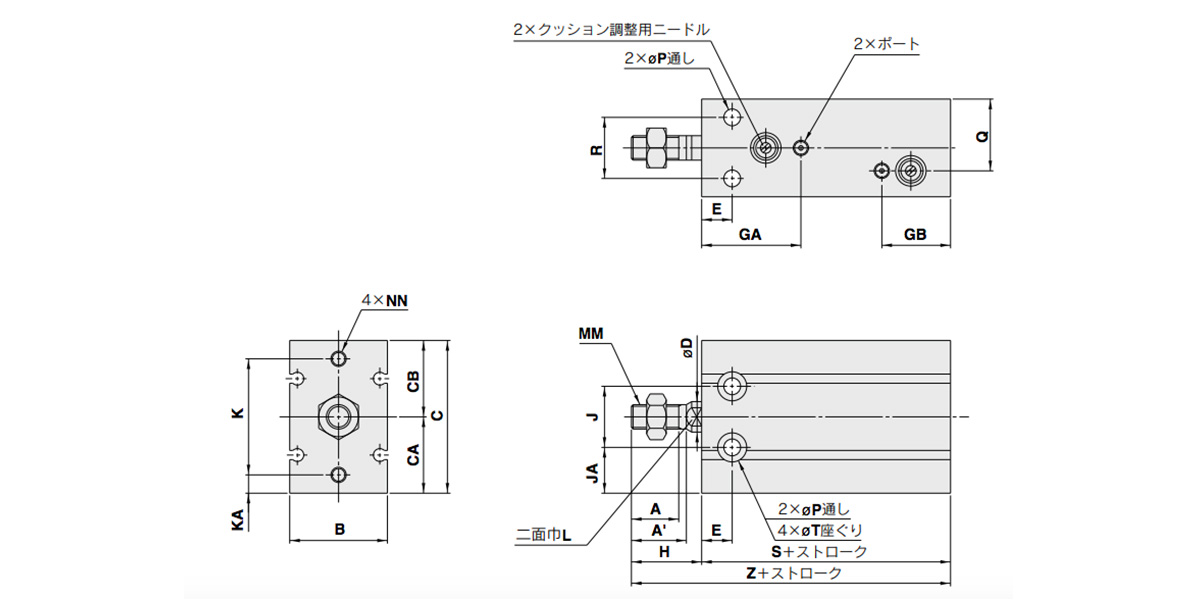
Dimensional drawings: CU Series Free Mount Cylinder With Air Cushion
(Units: mm)
| Tube inner diameter (mm) | Port | A | A' | B | C | CA | CB | D | E | GA | GB | H | J | JA |
|---|---|---|---|---|---|---|---|---|---|---|---|---|---|---|
| 20 | M5 × 0.8 | 12 | 14 | 26 | 42 | 20 | 22 | 8 | 9 | 29 | 27 | 19 | 16 | 12 |
| 25 | M5 × 0.8 | 15.5 | 18 | 32 | 50 | 25 | 25 | 10 | 10 | 32.5 | 22.5 | 23 | 20 | 15 |
| 32 | 1/8 | 19.5 | 22 | 40 | 62 | 31 | 31 | 12 | 11 | 35 | 25 | 27 | 24 | 19 |
(Units: mm)
| Tube inner diameter (mm) | K | KA | L | MM | NN | P | Q | R | T | S | Z | Standard Stroke |
|---|---|---|---|---|---|---|---|---|---|---|---|---|
| 20 | 30 | 5 | 6 | M6 × 1.0 | M5 × 0.8 depth 8 | 5.5 | 13 | 16 | 9.3 depth 8 | 53 | 72 | 20, 30, 40, 50, 60, 70, 80, 90, 100 |
| 25 | 38 | 6 | 8 | M8 × 1.25 | M5 × 0.8 depth 8 | 5.5 | 23.5 | 20 | 9.3 depth 9 | 51.5 | 74.5 | |
| 32 | 48 | 7 | 10 | M10 × 1.25 | M6 × 1.0 depth 9 | 6.6 | 29 | 24 | 11 depth 11.5 | 56 | 83 |
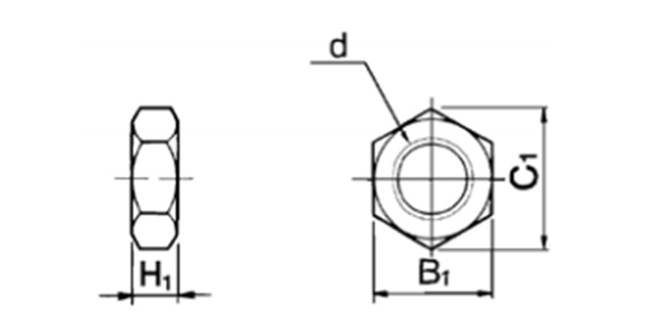
Dimensional drawings: rod-end nut / accessory
(Units: mm)
| Part No. | Applicable Tube Bore Size (mm) | d | H1 | B1 | C1 |
|---|---|---|---|---|---|
| NT-015A | 20 | M6 × 1.0 | 5 | 10 | 11.5 |
| NT-02 | 25 | M8 × 1.25 | 5 | 13 | 15.0 |
| NT-03 | 32 | M10 × 1.25 | 6 | 17 | 19.6 |
Material: carbon steel
Proper Auto Switch Mounting Position (Detection at Stroke End) and Mounting Height
(Units: mm)
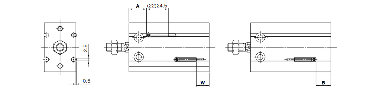
Dimensional drawings: D-A9□/D-M9□/D-M9□W/D-M9□A
*( ): denotes the values of D-A96.
(Units: mm)
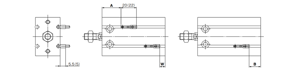
Dimensional drawings: D-A9□V/D-M9□V/D-M9□WV/D-M9□AV
*( ): denotes the values of D-M9□V/D-M9□WV.
(Units: mm)
| Tube inner diameter (mm) | D-A9□, D-A9□V | D-M9□, D-M9□W | D-M9□V, D-M9□WV | D-M9□A | D-M9□AV | ||||||||||
|---|---|---|---|---|---|---|---|---|---|---|---|---|---|---|---|
| A | B | W | A | B | W | A | B | W | A | B | W | A | B | W | |
| 20 | 18 | 15 | 13 (10.5) | 22 | 19 | 9 | 22 | 19 | 11 | 22 | 19 | 11 | 22 | 19 | 13 |
| 25 | 20 | 11 | 9 (6.5) | 24.5 | 15 | 5 | 24.5 | 15 | 7 | 24.5 | 15 | 7 | 24.5 | 15 | 9 |
| 32 | 22.5 | 13.5 | 11.5 (9) | 26.5 | 17.5 | 7.5 | 26.5 | 17.5 | 9.5 | 26.5 | 17.5 | 9.5 | 26.5 | 17.5 | 11.5 |
- *1Figures in the table above are used as a reference when mounting the auto switches for stroke end detection. When actually setting the auto switches, adjust them after confirming their operation.
- *2Values in ( ) under column W are dimensions for the D-A90 and D-A93 type.
Operating Range
D-A9□, D-A9□V
Bore size 20 mm: 11 mm / Bore size 25 mm: 12.5 mm / Bore size 32 mm: 14 mm
D-M9□, D-M9□V, D-M9□W, D-M9□WV, D-M9□A, D-M9□AV
Bore size 20 mm: 7 mm / Bore size 25 mm: 7 mm / Bore size 32 mm: 7.5 mm
*The operating range is provided as a guideline that includes hysteresis and is not a guaranteed value (assuming approximately ±30% dispersion). It may vary substantially depending on the ambient environment.
Mounting
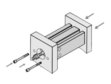
Axial mounting (body tapped)
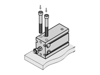
Vertical mounting (body through-holes)
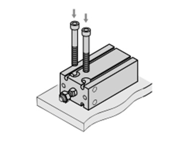
Lateral mounting (body through-holes)
Precautions
Installation and Removal of Retaining Rings
- *Use an appropriate pair of pliers (tool for installing a type C retaining ring) for installation and removal of retaining rings.
- *Even when using an appropriate pair of pliers (tool for installing a type C retaining ring), proceed with caution as there is a danger of the retaining ring flying off the end of the pliers (tool) and causing bodily injury or damage to nearby equipment. After installation, make sure that the retaining ring is securely seated into the retaining ring groove before supplying air.
Selection
- *Operate the cylinder to the stroke end. When the stroke is restricted by an external stopper or a clamped workpiece, sufficient cushioning and noise reduction may not be achieved.
- *Strictly observe the limiting ranges for load weight and maximum speed (Graph 1). Also, the limiting ranges provided here are based on the condition that the cylinder is operated to the stroke end with proper cushion needle adjustment. If operated beyond the limiting ranges, excessive impact will occur and this may cause damage to equipment.
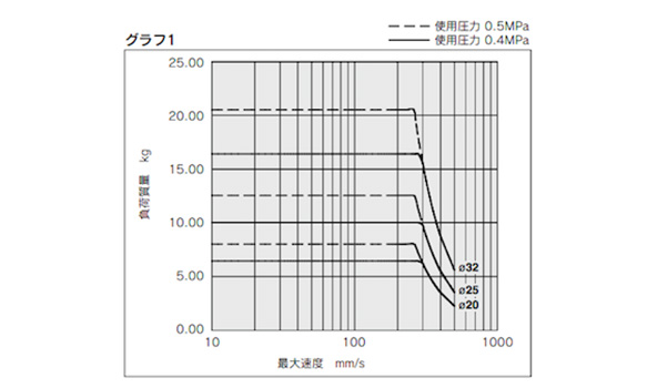
Limiting ranges for load weight and maximum speed (Graph 1)
*See the manufacturer's catalog for product information other than that detailed above.
| Part Number |
|---|
| CDU20-20A-M9BW |
| Part Number | Standard Unit Price | Minimum order quantity | Volume Discount | Days to Ship | Cylinder (Tube) Inner Diameter (Ø) | Stroke (mm) | Operating Temperature (°C) | Port thread type | Auto Switches | Lead Wire | The number of the switches | Connector type |
|---|---|---|---|---|---|---|---|---|---|---|---|---|
- | 1 Piece(s) | Quote | 20 | 20 | -10~60 | M5 × 0.8 | M9BW | 0.5 | 2 pcs. | None |
Loading...
Basic Information
| Cylinder Operation Method | Double Acting | Rod Operation Method | Single Rods | Main Body Shape | Plate Cylinder |
|---|---|---|---|---|---|
| Additional Function | Standard | Environment, Applications | Standard | End Locking | No |
| Valves | No | Operating Pressure(MPa) | 0.08::0.7 |
Please check the type/dimensions/specifications of the part CDU20-20A-M9BW in the CU Series Free Mount Cylinder With Air Cushion series.
Specification/Dimensions
-
type
- CDU20□
- CDU25□
- CDU32□
- CU20□
- CU25□
- CU32□
-
Cylinder (Tube) Inner Diameter(Ø)
-
Stroke(mm)
-
Port thread type
- G 1/8
- NPT 1/8
- Rc 1/8
- M5 × 0.8
-
Auto Switches
-
Lead Wire
- 0.5
- 1
- 3
- 5
- None
-
The number of the switches
-
Connector type
- M12-4 pin
- None
-
CAD
- 2D
- 3D
Days to Ship
-
- All
- 46 Day(s) or Less
Specify Alterations
- The specifications and dimensions of some parts may not be fully covered. For exact details, refer to manufacturer catalogs .
Similar Part Numbers
| Part Number |
|---|
| CDU20-100A-A93LS |
| CDU20-100A-A93V |
| CDU20-100A-M9B |
| CDU20-20A-M9BWL |
| CDU20-20A-M9BWM |
| CDU20-20A-M9BWSDPC |
| Part Number | Standard Unit Price | Minimum order quantity | Volume Discount | Days to Ship | Cylinder (Tube) Inner Diameter (Ø) | Stroke (mm) | Operating Temperature (°C) | Port thread type | Auto Switches | Lead Wire | The number of the switches | Connector type |
|---|---|---|---|---|---|---|---|---|---|---|---|---|
- | 1 Piece(s) | Quote | 20 | 100 | -10~60 | M5 × 0.8 | A93 | 3 | 1 pc. | None | ||
- | 1 Piece(s) | Quote | 20 | 100 | -10~60 | M5 × 0.8 | A93V | 0.5 | 2 pcs. | None | ||
- | 1 Piece(s) | Quote | 20 | 100 | -10~60 | M5 × 0.8 | M9B | 0.5 | 2 pcs. | None | ||
- | 1 Piece(s) | Quote | 20 | 20 | -10~60 | M5 × 0.8 | M9BW | 3 | 2 pcs. | None | ||
- | 1 Piece(s) | Quote | 20 | 20 | -10~60 | M5 × 0.8 | M9BW | 1 | 2 pcs. | None | ||
- | 1 Piece(s) | Quote | 20 | 20 | -10~60 | M5 × 0.8 | M9BW | 0.5 | 2 pcs. | M12-4 pin |
Tech Support
Payment Method
- Credit Card
- PayPal
- Bank Transfer
Social Media
MISUMI Contact
Copyright © MISUMI Corporation All Rights Reserved.
How can we improve?
How can we improve?