(!)Due to Microsoft's end of support for Internet Explorer 11 on 15/06/2022, this site does not support the recommended environment.
Instead, please kindly use other browsers like Google Chrome, Microsoft Edge or Mozilla Firefox.
50,000 Stock items for Same Day Ship Out.
All Categories
Categories
- Automation Components
A wide variety of standard and configurable components for factory automation engineers in industries such as automotive, semiconductor, packaging, medical and many more.
- Linear Motion
- Rotary Motion
- Connecting Parts
- Rotary Power Transmission
- Motors
- Conveyors & Material Handling
- Locating, Positioning, Jigs & Fixtures
- Inspection
- Sensors, Switches
- Pneumatics, Hydraulics
- Vacuum Components
- Hydraulic Equipment
- Discharging / Painting Devices
- Pipe, Tubes, Hoses & Fittings
- Modules, Units
- Heaters, Temperature Control
- Framing & Support
- Casters, Leveling Mounts, Posts
- Doors, Cabinet Hardware
- Springs, Shock Absorbers
- Adjusting, Fastening, Magnets
- Antivibration, Soundproofing Materials, Safety Products
- Fasteners
A good selection of accessories such as screws, bolts, washers and nuts that you may need for your daily engineering usage.
- Materials
Browse industrial materials ranging from heat insulating plates, sponges, to metal and plastic materials in different sizes to meet your various applications.
- Wiring Components
A wide variety of wiring parts for connecting and protecting control and PC parts including Connectors, Cables, Electric Wires, Crimping Terminals and more.
- LAN Cables / Industrial Network Cables
- Cables by Application
- Cables with Connectors
- RS232 / Personal Computers / AV Cables
- Wires/Cables
- Connectors (General Purpose)
- Crimp Terminals
- Zip Ties
- Cable Glands
- Cable Bushings/Clips/Stickers
- Screws/Spacers
- Cable Accessories
- Tubes
- Protection Tubes
- Ducts/Wiremolds
- General Purpose Tools
- Dedicated Tools
- Soldering Supplies
- Electrical & Controls
A wide variety of controls and PC parts for electrical engineers including Controls, Powers, PC parts and more.
- Cutting Tools
A wide variety of cutting tools for many uses and work materials including End Mills, Drills, Cutters, Reamers, Turning Tools and more.
- Carbide End Mills
- HSS End Mills
- Milling Cutter Inserts/Holders
- Customized Straight Blade End Mills
- Dedicated Cutters
- Turning Tools
- Drill Bits
- Screw-Hole-Related Tools
- Reamers
- Chamfering / Centering Tools
- Fixtures Related to Cutting Tools
- Step Drills
- Hole Saws
- Clean Key Cutters
- Core Drills (Tip Tools)
- Magnetic Drilling Machine Cutters
- Drill Bits for Electric Drilling Machines
- Woodworking Drill Cutters
- Drills for Concrete
- Processing Tools
A wide variety of tools and supplies used in processing including Machine Tools, Measurement Tools, Grinding and Polishing Supplies and more.
- Material Handling & Storage
A wide variety of goods used in shipment, material handling and warehouse including Tape supplies, Stretch film, Truck, Shelf, Crane and more.
- Tape Supplies
- Cushioning Materials
- Stretch Films
- Cardboard
- Plastic Bags
- PP Bands
- Magic Tapes / Tying Belts
- Rubber Bands
- Strings/Ropes
- Cable Ties
- Tags
- Labelers
- Unpacking Cutters
- Packing Support Equipment
- Cloth Sheets for Packing
- Conveyance/Dolly Carts
- Tool Wagons
- Tool Cabinets / Container Racks
- Lifters / Hand Pallets
- Container Pallets
- Storage Supplies
- Shelves/Racks
- Work Benches
- Suspended Clamps/Suspended Belts
- Jack Winches
- Chain Block Cranes
- Bottles/Containers
- Bicycle Storage Area
- Safety & General Supplies
A large variety of goods for every kind of factories and offices including Protection items, Cleaning supplies, sanitations, office supplies and more.
- Lab & Clean Room Supplies
A large variety of items used in R&D and Clean Room including research Equipment, Laboratory Essentials, Analysis Supplies, Clean Environment-Related Equipment and more.
- Press Die Components
Choose from thousands of standard stamping die components including Punch & Die, Gas Springs, Guide Components, Coil Springs and many more.
- Plastic Mold Components
Browse our wide variety of mold components including Ejector Pins, Sleeves, Leader Components, Sprue Bushings and many more.
- Ejector Pins
- Sleeves, Center Pins
- Core Pins
- Sprue bushings, Gates, and other components
- Date Mark Inserts, Recycle Mark Inserts, Pins with Gas Vent
- Undercut, Plates
- Leader Components, Components for Ejector Space
- Mold Opening Controllers
- Cooling or Heating Components
- Accessories, Others
- Components of Large Mold, Die Casting
- Injection Molding Components
Browse our injection molding components including Heating Items, Couplers, Hoses and more.
- Injection Molding Machine Products
- Accessories of Equipment
- Auxiliary Equipment
- Air Nippers
- Air Cylinders
- Air Chuck for Runner
- Chuck Board Components
- Frames
- Suction Components
- Parallel Air Chuck
- Special Air Chuck
- Chemical for Injection Molding
- Mold Maintenance
- Heating Items
- Heat Insulation Sheets
- Couplers, Plugs, One-touch Joints
- Tubes, Hoses, Peripheral Components
Search by Application
Brands


- Please be informed that our office is closed during the upcoming Labour Day Holiday in 2024. We would also like to inform you that there may be a potential delay in response/shipment from the supplier due to the Japan Golden Week holiday which falls from 29th April to 6th May 2024. Click here for details.
- Please Note our New Address (effective April 1, 2024): 331 North Bridge Rd, #05-01 Odeon 331, Singapore 188720.
Magnetically Coupled Rodless Cylinder, Linear Guide Type CY1H Series (CY1H10-100-Y7PVZ)
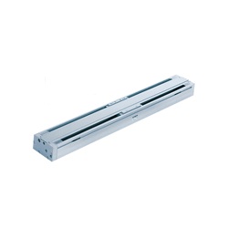
A CY1H Series magnetically coupled rodless cylinder with linear guide manufactured by SMC.
[Features]
· A space-saving type cylinder with a magnetically coupled design that allows use in wide range of applications.
(i)Caution
- Refer to the manufacturer's catalog for specification and material details.
- Product images may be representative images. Refer to the manufacturer's catalog for shape details.
- CAD data is not supported for some model numbers.
Part Number
Configured Part Number is shown.
CY1H10-100-Y7PVZ
Magnetically Coupled Rodless Cylinder, Linear Guide Type CY1H Series Specifications
Model Number Notation
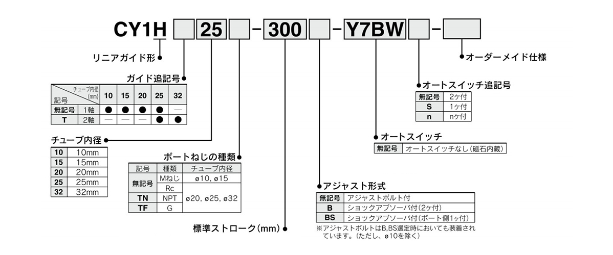
Model Number Notation
Shock Absorber Model Numbers
| Model | Type | Tube Internal Diameter (mm) | ||||
|---|---|---|---|---|---|---|
| 10 | 15 | 20 | 25 | 32 | ||
| CY1H | Standard (Shock Absorber RB Series) | RB0805 | RB0806 | RB1006 | RB1411 | - |
| Equipped with an RJ Series shock absorber / soft type (-XB22) | RJ0806H | RJ1007H | RJ1412H | - | ||
| CY1HT | Standard (Shock Absorber RB Series) | - | - | - | RB1411 | RB2015 |
| Equipped with an RJ Series shock absorber / soft type (-XB22) | - | - | - | RJ1412H | - | |
- *The lifespan of the shock absorber differs from that of the CY1H cylinder unit.
Specifications
| Tube Internal Diameter mm | 10 | 15 | 20 | 25 | 32 |
|---|---|---|---|---|---|
| Fluid | Air | ||||
| Operation Type | Double-acting type | ||||
| Maximum Operating Pressure | 0.7 MPa | ||||
| Minimum Operating Pressure | 0.2 MPa | ||||
| Guaranteed Proof Pressure | 1.05 MPa | ||||
| Ambient Temperature and Operating Fluid Temperature | -10°C to +60°C (no freezing) | ||||
| Piston Speed | 70 to 500 mm/s | ||||
| Cushioning (External Stopper) | Urethane bumper at both ends (standard), shock absorber (options) | ||||
| Lubrication | Not required (lubrication-free) | ||||
| Stroke Length Tolerance | 0 to 1.8 mm | ||||
| Holding Force (N) | 53.9 | 137 | 231 | 363 | 588 |
| Piping | Centralized piping type | ||||
| Piping connection port diameter | M5 × 0.8 | Rc 1/8 | |||
Standard Stroke Table
| Tube Inner Diameter (mm) | Number of Axes | Standard Stroke (mm) * | Maximum Manufacturable Stroke (mm) |
|---|---|---|---|
| 10 | 1 Axis | 100, 200, 300 | 500 |
| 15 | 100, 200, 300, 400, 500 | 750 | |
| 20 | 100, 200, 300, 400, 500, 600 | 1,000 | |
| 25 | 100, 200, 300, 400, 500, 600, 800 | 1,200 | |
| 25 | 2 Axis | 100, 200, 300, 400, 500, 600, 800, 1,000 | |
| 32 | 1,500 |
- *The stroke is manufacturable in 1 mm increments, up to the maximum stroke. However, for intermediate strokes other than the standard stroke, add the "-XB10" suffix to the model number. For those exceeding the standard stroke up to the maximum manufacturable stroke, add the "XB11" suffix to the model number.
Structural Drawing Examples
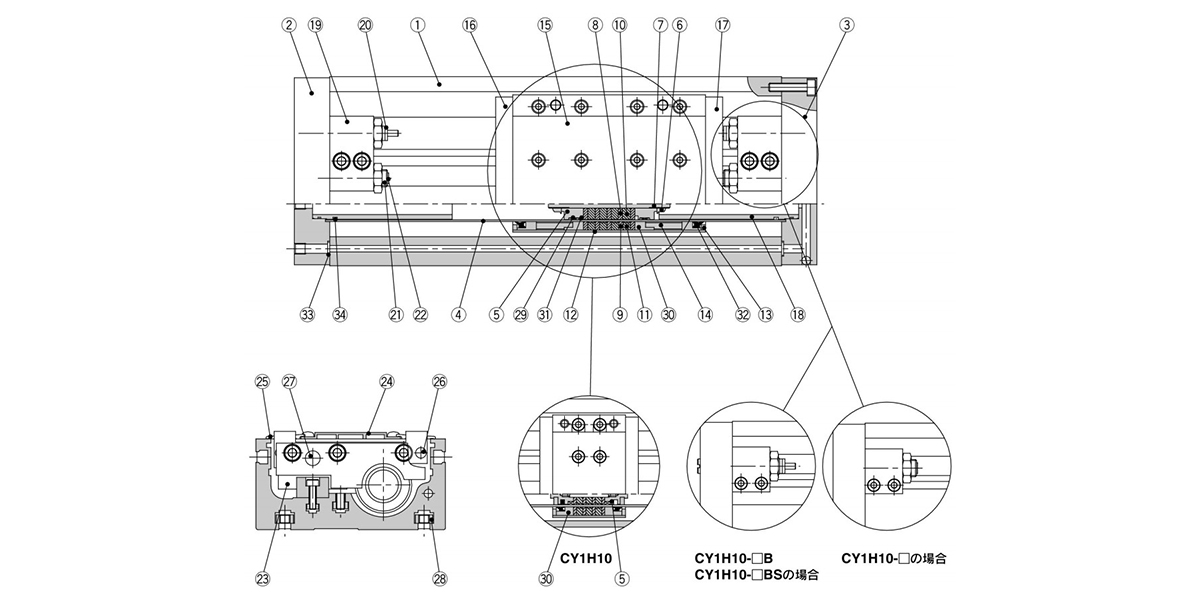
Single-axis type CY1H structural drawing
Component Parts
| Number | Part name | Material | Note |
|---|---|---|---|
| 1 | Rail base | Aluminum alloy | Anodized aluminum |
| 2 | Plate A | Aluminum alloy | Anodized |
| 3 | Plate B | Aluminum alloy | Anodized |
| 4 | Cylinder Tube | Stainless steel | - |
| 5 | Piston | Aluminum alloy | Chromate |
| 6 | Piston Nut | Carbon steel | Zinc chromate (Excluding CY1H10, 15) |
| 7 | Shaft | Stainless steel | - |
| 8 | Piston-Side Yoke | Rolled steel plate | Zinc chromate |
| 9 | External Slider Side Yoke | Rolled steel plate | Zinc chromate |
| 10 | Magnet A | - | - |
| 11 | Magnet B | - | - |
| 12 | External Slider Tube | Aluminum alloy | - |
| 13 | Spacer | Rolled steel plate | Nickel plating |
| 14 | Spaced Ring | Aluminum alloy | Chromate (excludes CY1H10) |
| 15 | Slide table | Aluminum alloy | Anodized |
| 16 | Side Plate A | Aluminum alloy | Anodized |
| 17 | Side Plate B | Aluminum alloy | Anodized |
| 18 | Internal Stopper | Aluminum alloy | Anodized |
| 19 | Stopper | Aluminum alloy | Anodized |
| 20 | Shock Absorber | - | RB Series |
| 21 | Adjustment Bolt | Chrome molybdenum steel | Nickel plating |
| 22 | Adjustment Bumper | Urethane rubber | - |
| 23 | Linear Guide | - | - |
| 24 | Top Cover | Aluminum alloy | Anodized |
| 25 | Dust Cover | Special resin | - |
| 26 | Magnet (for Auto Switches) | - | - |
| 27 | Parallel Pin | Carbon steel | Nickel plating |
| 28 | Square Nuts for Unit Mounting | Carbon steel | Nickel plating |
| *29 | Wear Ring A | Special resin | - |
| *30 | Wear Ring B | Special resin | - |
| *31 | Piston Seal | NBR | - |
| *32 | Scraper | NBR | - |
| *33 | O-ring | NBR | - |
| *34 | O-ring | NBR | - |
*There are 4 square nuts provided for mounting the main unit, regardless of the stroke.
Magnetically Coupled Rodless Cylinder, Linear Guide Type, CY1H Series, Example Dimensions
(Unit: mm)
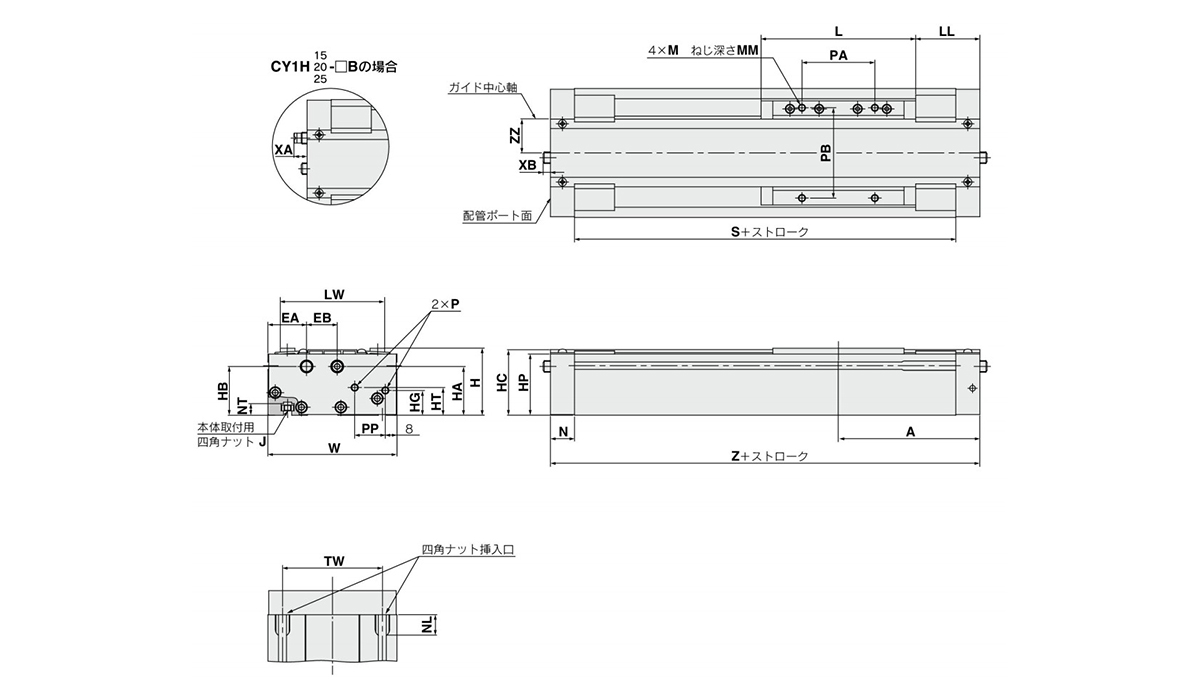
Single axis type / ø10 mm (internal diameter) dimensional drawing
| Model | A | EA | EB | H | HA | HB | HC | HG | HP | HT | J | L | LL | LW | M | MM | N | NL | NT |
|---|---|---|---|---|---|---|---|---|---|---|---|---|---|---|---|---|---|---|---|
| CY1H15 | 97 | 26.5 | 21 | 46 | 33.5 | 33.5 | 45 | 17 | 42 | 19 | M5 × 0.8 | 106 | 44 | 71.5 | M5 × 0.8 | 8 | 16.5 | 15 | 8 |
| CY1H20 | 102.5 | 26.5 | 22 | 54 | 42.5 | 41.5 | 53 | 16 | 50 | 23.5 | M5 × 0.8 | 108 | 48.5 | 75.5 | M5 × 0.8 | 8 | 18 | 15 | 8 |
| CY1H25 | 125 | 29 | 24 | 63 | 46 | 46 | 61.5 | 25 | 58.5 | 28 | M6 × 1.0 | 138 | 56 | 86 | M6 × 1.0 | 10 | 20.5 | 18 | 9 |
| Model | P | PA | PB | PP | S | TW | W | XA | XB | Z | ZZ |
|---|---|---|---|---|---|---|---|---|---|---|---|
| CY1H15 | M5 × 0.8 | 50 | 62 | 21 | 161 | 65 | 88.5 | - | - | 194 | 17.5 |
| CY1H20 | Rc 1/8 | 50 | 65 | 23 | 169 | 70 | 92.5 | - | - | 205 | 19.5 |
| CY1H25 | Rc 1/8 | 65 | 75 | 27 | 209 | 75 | 103 | 11.3 | 9.5 | 250 | 23.5 |
Usage Precautions
- *When within the allowable range, direct load can be applied. But when connecting with a load having a guide mechanism on the exterior, full center alignment work is required.
- *Guides are adjusted before shipping. Take care not to move the settings of the adjustment portion unintentionally.
- *Can be used without lubrication. If lubricating, use turbine oil class 1 (no additives) ISO VG32. (Machine oil and spindle oil cannot be used)
- *Avoid use in environments that may cause the degradation of cylinder sliding part lubricity. This includes environments where liquids such as water or machining fluids are dispersed within the cylinder, environments where water vapor is present or those environments where the adherence of contaminants or dust on the cylinder may be a concern.
- *Do not use if the magnet coupling has become unaligned or detached.
- *Never disassemble the magnet structure (piston slider, external slider).
| Part Number |
|---|
| CY1H10-100-Y7PVZ |
| Part Number | Standard Unit Price | Minimum order quantity | Volume Discount | Days to Ship | Stroke (mm) | Max. Load Mass (Horizontal Mounting) (kg) | Max. Load Mass (kg) | Table Size: Length L (mm) | Cylinder I.D. (Ø) | Guide Type | Table Size: Width W (mm) | Table Size: Height H (mm) | Port Screw Type | Adjuster Option | Auto Switches | Lead Wire Length (m) | Lead Wire Connector | The number of the switches | Made-to-order |
|---|---|---|---|---|---|---|---|---|---|---|---|---|---|---|---|---|---|---|---|
- | 1 Piece(s) | Quote | 100 | 1~4.9 | 4 | 46 | 10 | [Rolling Guide] Linear guide 1 axis | 54 | 39.5 | M screw | Adjusting bolt included | Y7PV | 5 | - | 2 | None |
Loading...
Basic Information
| Type | Rodless Cylinder | Table Material | Aluminum Alloy | Rodless Cylinder Joint Type | Magnetic |
|---|---|---|---|---|---|
| Environment | General Purpose | Table Surface Treatment | Alumite | Piping Format | Centralized piping type |
| Specifications | Magnet built-in | Custom-made Specifications | 0.2 to 0.7 |
Please check the type/dimensions/specifications of the part CY1H10-100-Y7PVZ in the Magnetically Coupled Rodless Cylinder, Linear Guide Type CY1H Series series.
Specification/Dimensions
-
Lead Wire Connector
- M8 3‑pin plug connector
- M8 4‑pin plug connector
- M12 4‑pin A cord (normal key) plug connector
-
type
- CY1H
- CY1HT
-
Stroke(mm)
- 1,000
- 1,050
- 1,100
- 1,200
- 1,300
- 1,500
- 100
- 105
- 110
- 120
- 125
- 130
- 135
- 140
- 145
- 150
- 151
- 155
- 160
- 165
- 170
- 175
- 180
- 190
- 195
- 200
- 205
- 210
- 215
- 220
- 225
- 230
- 235
- 240
- 250
- 254
- 255
- 260
- 265
- 270
- 275
- 280
- 285
- 290
- 300
- 305
- 310
- 315
- 320
- 325
- 330
- 335
- 340
- 350
- 355
- 360
- 365
- 370
- 372
- 374
- 375
- 380
- 390
- 400
- 410
- 415
- 420
- 425
- 430
- 435
- 440
- 450
- 455
- 460
- 465
- 468
- 470
- 472
- 475
- 476
- 480
- 485
- 490
- 495
- 499
- 500
- 510
- 520
- 525
- 530
- 540
- 550
- 560
- 570
- 580
- 600
- 620
- 630
- 635
- 640
- 650
- 660
- 680
- 690
- 700
- 710
- 720
- 730
- 750
- 760
- 770
- 780
- 790
- 800
- 810
- 820
- 825
- 830
- 850
- 860
- 880
- 890
- 900
- 910
- 920
- 930
- 950
- 960
- 1020
- 1040
- 1150
- 1170
- 1245
- 1250
- 1400
-
Max. Load Mass (Horizontal Mounting)(kg)
-
Max. Load Mass(kg)
-
Table Size: Length L(mm)
-
Cylinder I.D.(Ø)
-
Guide Type
- Rolling Guide
- Rolling Guide
-
Table Size: Width W(mm)
-
Table Size: Height H(mm)
-
Port Screw Type
-
Adjuster Option
-
Auto Switches
-
Lead Wire Length(m)
- 0.5
- 1
- 3
- 5
-
The number of the switches
- 1
- 2
- 3
- 4
- 5
- 6
- 7
- 8
-
Made-to-order
- Helical coil insert thread specification
- Intermediate stroke (using dedicated body)
- Long-stroke type
- None
- Shock absorber / soft-type RJ Series mounted cylinder
-
CAD
- 2D
- 3D
Days to Ship
-
- All
- 46 Day(s) or Less
Specify Alterations
- The specifications and dimensions of some parts may not be fully covered. For exact details, refer to manufacturer catalogs .
Similar Part Numbers
| Part Number |
|---|
| CY1H10-100-Y59ALS |
| CY1H10-100-Y59AS |
| CY1H10-100-Y59AZ |
| CY1H10-100-Y7PVZS |
| CY1H10-100-Y7PW |
| CY1H10-100-Y7PWL |
| Part Number | Standard Unit Price | Minimum order quantity | Volume Discount | Days to Ship | Stroke (mm) | Max. Load Mass (Horizontal Mounting) (kg) | Max. Load Mass (kg) | Table Size: Length L (mm) | Cylinder I.D. (Ø) | Guide Type | Table Size: Width W (mm) | Table Size: Height H (mm) | Port Screw Type | Adjuster Option | Auto Switches | Lead Wire Length (m) | Lead Wire Connector | The number of the switches | Made-to-order |
|---|---|---|---|---|---|---|---|---|---|---|---|---|---|---|---|---|---|---|---|
- | 1 Piece(s) | Quote | 100 | 1~4.9 | 4 | 46 | 10 | [Rolling Guide] Linear guide 1 axis | 54 | 39.5 | M screw | Adjusting bolt included | Y59A | 3 | - | 1 | None | ||
- | 1 Piece(s) | Quote | 100 | 1~4.9 | 4 | 46 | 10 | [Rolling Guide] Linear guide 1 axis | 54 | 39.5 | M screw | Adjusting bolt included | Y59A | 0.5 | - | 1 | None | ||
- | 1 Piece(s) | Quote | 100 | 1~4.9 | 4 | 46 | 10 | [Rolling Guide] Linear guide 1 axis | 54 | 39.5 | M screw | Adjusting bolt included | Y59A | 5 | - | 2 | None | ||
- | 1 Piece(s) | Quote | 100 | 1~4.9 | 4 | 46 | 10 | [Rolling Guide] Linear guide 1 axis | 54 | 39.5 | M screw | Adjusting bolt included | Y7PV | 5 | - | 1 | None | ||
- | 1 Piece(s) | Quote | 100 | 1~4.9 | 4 | 46 | 10 | [Rolling Guide] Linear guide 1 axis | 54 | 39.5 | M screw | Adjusting bolt included | Y7PW | 0.5 | - | 2 | None | ||
- | 1 Piece(s) | Quote | 100 | 1~4.9 | 4 | 46 | 10 | [Rolling Guide] Linear guide 1 axis | 54 | 39.5 | M screw | Adjusting bolt included | Y7PW | 3 | - | 2 | None |
Tech Support
Payment Method
- Credit Card
- PayPal
- Bank Transfer
Social Media
MISUMI Contact
Copyright © MISUMI Corporation All Rights Reserved.
How can we improve?
How can we improve?