(!)Due to Microsoft's end of support for Internet Explorer 11 on 15/06/2022, this site does not support the recommended environment.
Instead, please kindly use other browsers like Google Chrome, Microsoft Edge or Mozilla Firefox.
50,000 Stock items for Same Day Ship Out.
All Categories
Categories
- Automation Components
A wide variety of standard and configurable components for factory automation engineers in industries such as automotive, semiconductor, packaging, medical and many more.
- Linear Motion
- Rotary Motion
- Connecting Parts
- Rotary Power Transmission
- Motors
- Conveyors & Material Handling
- Locating, Positioning, Jigs & Fixtures
- Inspection
- Sensors, Switches
- Pneumatics, Hydraulics
- Vacuum Components
- Hydraulic Equipment
- Discharging / Painting Devices
- Pipe, Tubes, Hoses & Fittings
- Modules, Units
- Heaters, Temperature Control
- Framing & Support
- Casters, Leveling Mounts, Posts
- Doors, Cabinet Hardware
- Springs, Shock Absorbers
- Adjusting, Fastening, Magnets
- Antivibration, Soundproofing Materials, Safety Products
- Fasteners
A good selection of accessories such as screws, bolts, washers and nuts that you may need for your daily engineering usage.
- Materials
Browse industrial materials ranging from heat insulating plates, sponges, to metal and plastic materials in different sizes to meet your various applications.
- Wiring Components
A wide variety of wiring parts for connecting and protecting control and PC parts including Connectors, Cables, Electric Wires, Crimping Terminals and more.
- LAN Cables / Industrial Network Cables
- Cables by Application
- Cables with Connectors
- RS232 / Personal Computers / AV Cables
- Wires/Cables
- Connectors (General Purpose)
- Crimp Terminals
- Zip Ties
- Cable Glands
- Cable Bushings/Clips/Stickers
- Screws/Spacers
- Cable Accessories
- Tubes
- Protection Tubes
- Ducts/Wiremolds
- General Purpose Tools
- Dedicated Tools
- Soldering Supplies
- Electrical & Controls
A wide variety of controls and PC parts for electrical engineers including Controls, Powers, PC parts and more.
- Cutting Tools
A wide variety of cutting tools for many uses and work materials including End Mills, Drills, Cutters, Reamers, Turning Tools and more.
- Carbide End Mills
- HSS End Mills
- Milling Cutter Inserts/Holders
- Customized Straight Blade End Mills
- Dedicated Cutters
- Turning Tools
- Drill Bits
- Screw-Hole-Related Tools
- Reamers
- Chamfering / Centering Tools
- Fixtures Related to Cutting Tools
- Step Drills
- Hole Saws
- Clean Key Cutters
- Core Drills (Tip Tools)
- Magnetic Drilling Machine Cutters
- Drill Bits for Electric Drilling Machines
- Woodworking Drill Cutters
- Drills for Concrete
- Processing Tools
A wide variety of tools and supplies used in processing including Machine Tools, Measurement Tools, Grinding and Polishing Supplies and more.
- Material Handling & Storage
A wide variety of goods used in shipment, material handling and warehouse including Tape supplies, Stretch film, Truck, Shelf, Crane and more.
- Tape Supplies
- Cushioning Materials
- Stretch Films
- Cardboard
- Plastic Bags
- PP Bands
- Magic Tapes / Tying Belts
- Rubber Bands
- Strings/Ropes
- Cable Ties
- Tags
- Labelers
- Unpacking Cutters
- Packing Support Equipment
- Cloth Sheets for Packing
- Conveyance/Dolly Carts
- Tool Wagons
- Tool Cabinets / Container Racks
- Lifters / Hand Pallets
- Container Pallets
- Storage Supplies
- Shelves/Racks
- Work Benches
- Suspended Clamps/Suspended Belts
- Jack Winches
- Chain Block Cranes
- Bottles/Containers
- Bicycle Storage Area
- Safety & General Supplies
A large variety of goods for every kind of factories and offices including Protection items, Cleaning supplies, sanitations, office supplies and more.
- Lab & Clean Room Supplies
A large variety of items used in R&D and Clean Room including research Equipment, Laboratory Essentials, Analysis Supplies, Clean Environment-Related Equipment and more.
- Press Die Components
Choose from thousands of standard stamping die components including Punch & Die, Gas Springs, Guide Components, Coil Springs and many more.
- Plastic Mold Components
Browse our wide variety of mold components including Ejector Pins, Sleeves, Leader Components, Sprue Bushings and many more.
- Ejector Pins
- Sleeves, Center Pins
- Core Pins
- Sprue bushings, Gates, and other components
- Date Mark Inserts, Recycle Mark Inserts, Pins with Gas Vent
- Undercut, Plates
- Leader Components, Components for Ejector Space
- Mold Opening Controllers
- Cooling or Heating Components
- Accessories, Others
- Components of Large Mold, Die Casting
- Injection Molding Components
Browse our injection molding components including Heating Items, Couplers, Hoses and more.
- Injection Molding Machine Products
- Accessories of Equipment
- Auxiliary Equipment
- Air Nippers
- Air Cylinders
- Air Chuck for Runner
- Chuck Board Components
- Frames
- Suction Components
- Parallel Air Chuck
- Special Air Chuck
- Chemical for Injection Molding
- Mold Maintenance
- Heating Items
- Heat Insulation Sheets
- Couplers, Plugs, One-touch Joints
- Tubes, Hoses, Peripheral Components
Search by Application
Brands


- Please be informed that our operating hours are from 9:00~15:00 during the upcoming Vesak Day Holiday 2024. Click here for details.
- Please Note our New Address (effective April 1, 2024): 331 North Bridge Rd, #05-01 Odeon 331, Singapore 188720.
Mechanically Jointed Rodless Cylinder With Protective Cover, MY1□W Series (MY1CW20-150)
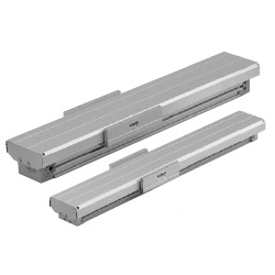
An air slide table made by SMC
[Features]
· Improved dust-proofing and water resistance for use in environments where dust and water are present in the air.
· The base cylinder option can be used as is
· A cover unit and a side seal unit can be retrofitted to the conventional MY1M/MY1C series
· Compact design with a suppressed overall length
· A non-contact auto switch can be mounted for improved water resistance
(i)Caution
- Refer to the catalog for product specifications.
- Product pictures are representations. CAD data is not supported by some of the model numbers.
Part Number
Configured Part Number is shown.
MY1CW20-150
Specifications of Mechanical Joint Type Rodless Cylinder With Protective Cover MY1□W Series
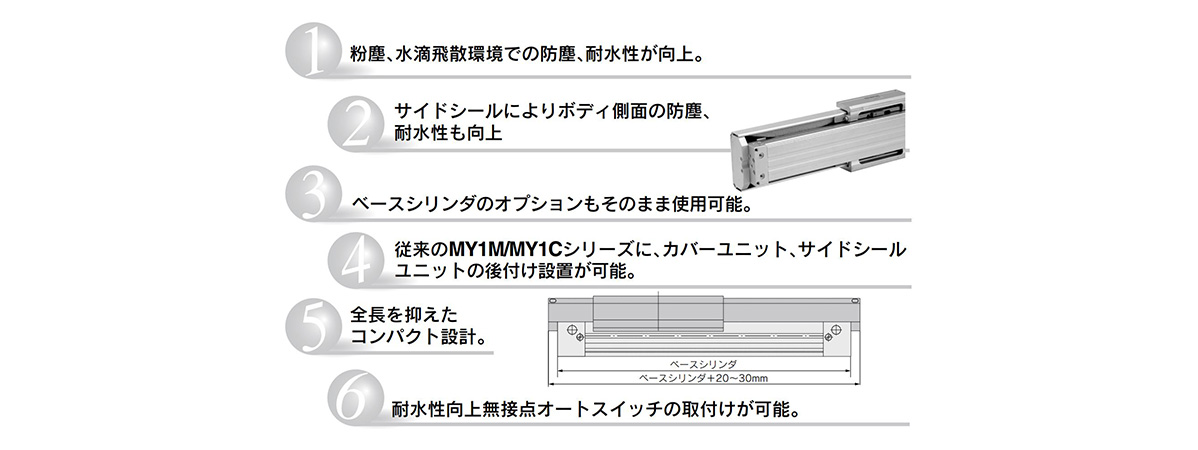
Features of Mechanical Joint Type Rodless Cylinder With Protective Cover MY1□W Series
Model Number Notation
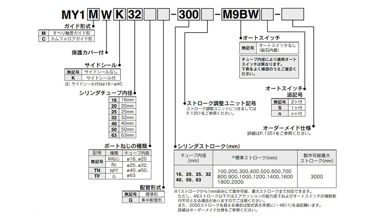
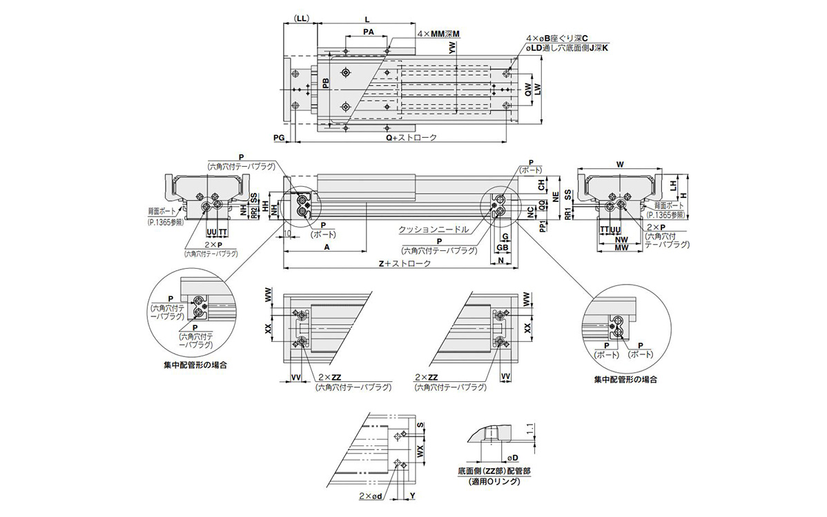
How to order: image
Specifications Table
| Tube Internal Diameter (mm) | 16 | 20 | 25 | 32 | 40 | 50 | 63 | |
|---|---|---|---|---|---|---|---|---|
| Fluid | Air | |||||||
| Operation Type | Double-acting type | |||||||
| Operating Pressure Range | MY1MW: 0.15 to 0.8 MPa, MY1CW: 0.1 to 0.8 MPa | |||||||
| Proof Pressure | 1.2 MPa | |||||||
| Ambient and fluid temperature | 5 to 60°C | |||||||
| Cushioning | Air cushion | |||||||
| Lubrication | Not required | |||||||
| Stroke Length Tolerance | 1,000 or less (0~+1.8) 1000 to 3000 (0~+2.8) | 2700 or less (0 to +1.8), 2,701 to 3,000 (0~+2.8) | ||||||
| Piping Connection Port Diameter | Front/side port | M5 × 0.8 | Rc 1/8 | Rc 1/4 | Rc3/8 | |||
| Bottom port | ø4 (Port size 4 mm) | ø6 (Port size 6 mm) | ø8 (Port size 8 mm) | ø10 (Port size 10 mm) | ||||
- * The stroke fine adjustment range is the adjustment range on one side when mounted on the cylinder.
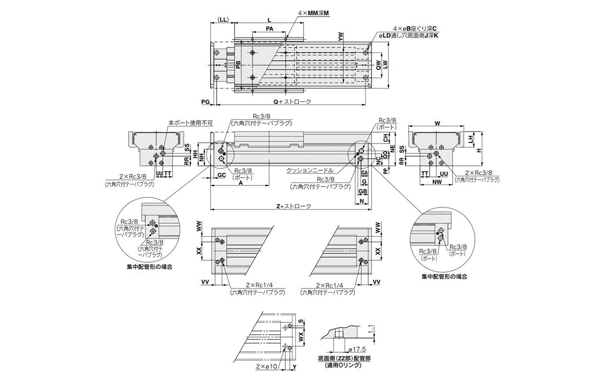
Dimensional Drawing
ø16 (tube inner diameter: 16 mm), ø20 (Tube inner diameter: 20 mm)
(Units: mm)
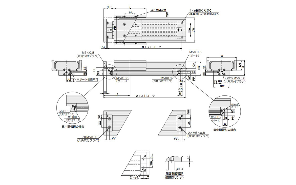
Dimensional drawing of ø16 (tube inner diameter: 16 mm) and ø20 (tube inner diameter: 20 mm)
(Units: mm)
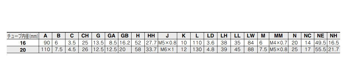
Image of dimensions table (A to NH) for tube inner diameter: 16 mm / 20 mm
(Units: mm)
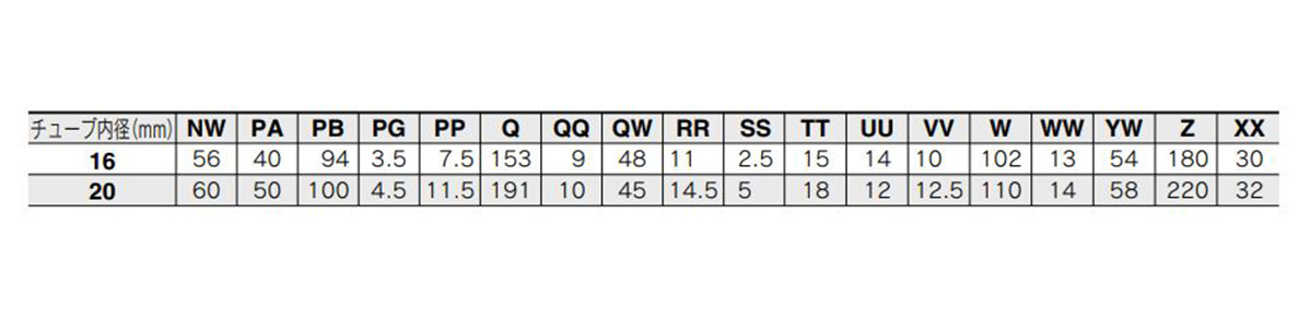
Image of dimensions table (NW to XX) for tube inner diameter: 16 mm / 20 mm
Piping hole dimension table for centralized bottom piping
* Please process this on the mounting side.
(Units: mm)
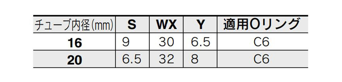
Image of piping hole dimensions for centralized piping on the bottom of the tube with inner diameter of 16 mm / 20 mm
ø25 (tube inner diameter: 25 mm), ø32 (tube inner diameter: 32 mm), ø40 (Tube inner diameter: 40 mm)
(Units: mm)
Dimensional drawing of ø25 (tube inner diameter: 25 mm), ø32 (tube inner diameter: 32 mm), ø40 (tube inner diameter: 40 mm)
(Units: mm)
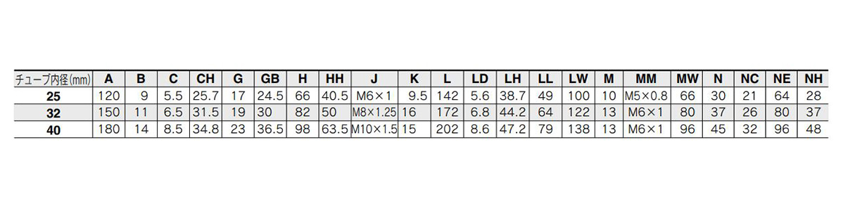
Image of dimensions table (A to NH) for tube inner diameter: 25 mm / 32 mm / 40 mm
(Units: mm)
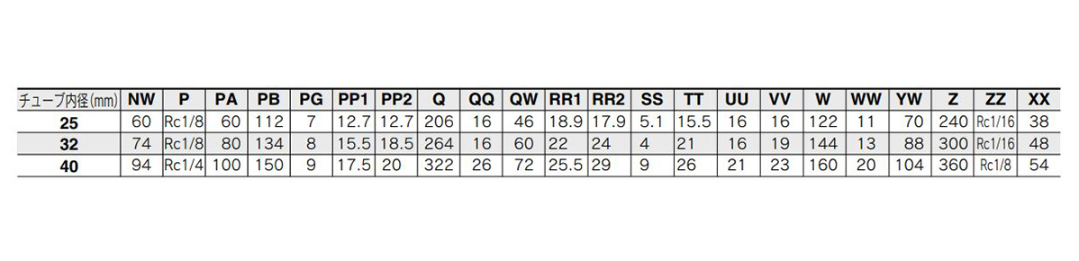
Image of dimensions table (NW to XX) for tube inner diameter: 25 mm / 32 mm / 40 mm
Piping hole dimension table for centralized bottom piping
* Please process this on the mounting side.
(Units: mm)
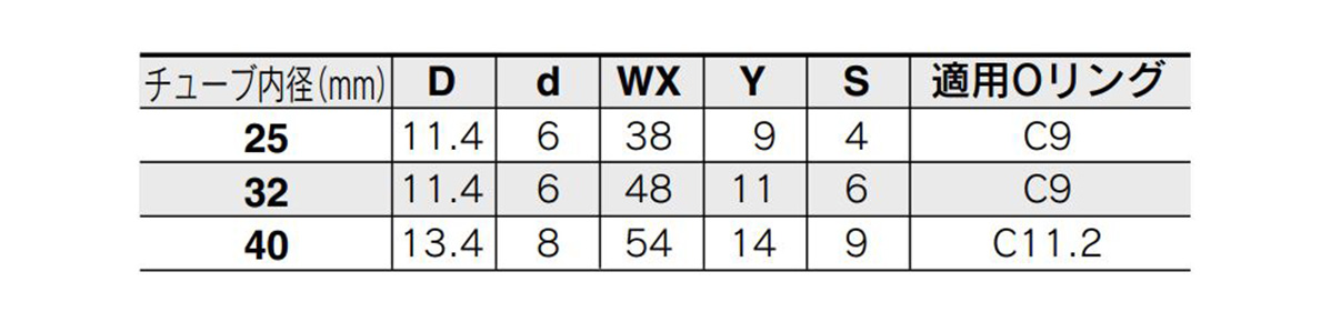
Image of piping hole dimension table for centralized bottom piping of the tube with inner diameter of 25 mm / 32 mm / 40 mm
ø50 (tube inner diameter: 50 mm), ø63 (Tube inner diameter: 63 mm)
(Units: mm)
Dimensional drawing of ø50 (tube inner diameter: 50 mm) and ø63 (tube inner diameter: 63 mm)
(Units: mm)
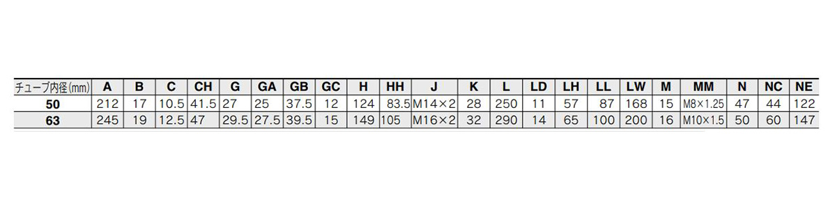
Image of dimensions table (A to NE) for tube inner diameter: 50 mm / 63 mm
(Units: mm)
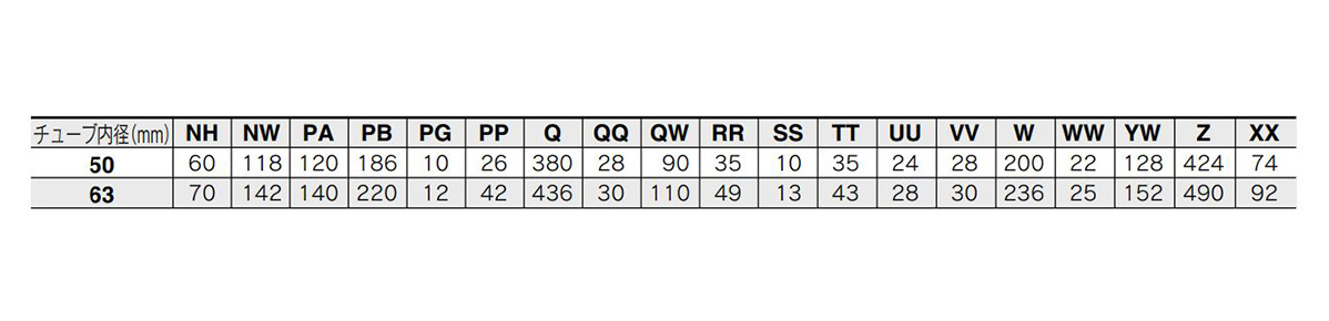
Image of dimensions table (NH to XX) for tube inner diameter: 50 mm / 63 mm
Piping hole dimension table for centralized bottom piping
* Please process this on the mounting side.
(Units: mm)

Piping hole dimension table for centralized bottom piping of the tube with inner diameter of 50 mm / 63 mm
Please refer to the table below for details about lead wire / connector specifications.

| Part Number |
|---|
| MY1CW20-150 |
| Part Number | Standard Unit Price | Minimum order quantity | Volume Discount | Days to Ship | Stroke (mm) | Max. Load Mass (Horizontal Mounting) (kg) | Max. Load Mass (kg) | Table Size: Length L (mm) | Cylinder I.D. (Ø) | Guide Type | Table Size: Width W (mm) | Table Size: Height H (mm) | Side Seal | Piping Format | Port Screw Type | Auto Switches | Lead Wire Length (m) | Lead Wire Connector | The number of the switches | Custom-made Specifications | Stroke adjustment unit symbol | Made-to-order |
|---|---|---|---|---|---|---|---|---|---|---|---|---|---|---|---|---|---|---|---|---|---|---|
- | 1 Piece(s) | Quote | 150 | 20~39.9 | 25 | 130 | 20 | [Rolling Guide] Cam Follower guide type | 88 | 58 | None | Standard type | M screw | None | - | - | - | 0.1 to 0.8 | No unit | None |
Loading...
Basic Information
| Type | Rodless Cylinder | Table Material | Aluminum Alloy | Rodless Cylinder Joint Type | Mechanically Jointed |
|---|---|---|---|---|---|
| Environment | Water Resistance / Dust Proofing | Table Surface Treatment | Hard Anodize | Cushion | Air cushion |
| Specifications | Magnet built-in |
Please check the type/dimensions/specifications of the part MY1CW20-150 in the Mechanically Jointed Rodless Cylinder With Protective Cover, MY1□W Series series.
Specification/Dimensions
-
Lead Wire Length(m)
- 0.5
- 1
- 3
- 5
-
Lead Wire Connector
- M8 3‑pin plug connector
- M8 4‑pin plug connector
- M12 4‑pin A cord (normal key) plug connector
-
The number of the switches
- 1
- 2
- 3
- 4
- 5
- 6
- 7
- 8
- 9
-
type
- MY1CW
- MY1MW
-
Stroke(mm)
- 1,000
- 1,005
- 1,025
- 1,050
- 1,070
- 1,100
- 1,200
- 1,300
- 1,370
- 1,500
- 1,580
- 1,700
- 1,800
- 1,870
- 1,900
- 2,000
- 2,004
- 2,500
- 3,000
- 50
- 60
- 65
- 70
- 75
- 77
- 80
- 90
- 100
- 110
- 115
- 120
- 121
- 122
- 125
- 130
- 135
- 140
- 150
- 155
- 160
- 164
- 165
- 170
- 175
- 180
- 185
- 190
- 200
- 202
- 205
- 210
- 214
- 215
- 220
- 225
- 230
- 232
- 235
- 240
- 245
- 250
- 254
- 255
- 260
- 265
- 270
- 275
- 276
- 280
- 285
- 290
- 300
- 306
- 310
- 315
- 320
- 325
- 330
- 335
- 336
- 340
- 345
- 350
- 354
- 356
- 360
- 365
- 368
- 370
- 375
- 378
- 380
- 385
- 390
- 392
- 400
- 405
- 410
- 420
- 425
- 430
- 435
- 440
- 441
- 445
- 450
- 455
- 460
- 465
- 470
- 475
- 480
- 485
- 490
- 495
- 500
- 504
- 508
- 510
- 520
- 530
- 534
- 535
- 540
- 545
- 550
- 555
- 560
- 565
- 570
- 571
- 575
- 580
- 590
- 600
- 610
- 615
- 620
- 625
- 630
- 633
- 635
- 640
- 645
- 650
- 655
- 660
- 670
- 675
- 680
- 690
- 695
- 700
- 710
- 715
- 718
- 720
- 725
- 730
- 735
- 736
- 737
- 740
- 745
- 750
- 755
- 760
- 762
- 765
- 770
- 775
- 780
- 785
- 787
- 790
- 796
- 800
- 805
- 807
- 810
- 812
- 820
- 823
- 824
- 825
- 830
- 831
- 838
- 840
- 845
- 850
- 858
- 860
- 865
- 870
- 875
- 880
- 881
- 884
- 885
- 887
- 896
- 900
- 910
- 912
- 914
- 915
- 920
- 922
- 930
- 935
- 936
- 940
- 941
- 945
- 950
- 955
- 960
- 965
- 970
- 975
- 980
- 988
- 990
- 1010
- 1015
- 1016
- 1020
- 1030
- 1040
- 1055
- 1060
- 1065
- 1075
- 1080
- 1088
- 1090
- 1105
- 1110
- 1120
- 1128
- 1139
- 1140
- 1150
- 1160
- 1170
- 1175
- 1176
- 1180
- 1195
- 1215
- 1220
- 1225
- 1230
- 1250
- 1255
- 1260
- 1270
- 1280
- 1290
- 1295
- 1305
- 1310
- 1315
- 1320
- 1330
- 1340
- 1350
- 1355
- 1360
- 1375
- 1380
- 1387
- 1400
- 1406
- 1410
- 1420
- 1430
- 1440
- 1450
- 1451
- 1475
- 1480
- 1485
- 1490
- 1520
- 1524
- 1525
- 1530
- 1540
- 1550
- 1560
- 1565
- 1585
- 1590
- 1600
- 1606
- 1610
- 1620
- 1650
- 1660
- 1675
- 1680
- 1720
- 1725
- 1740
- 1750
- 1760
- 1770
- 1820
- 1850
- 1880
- 1888
- 1890
- 1910
- 1930
- 1940
- 1950
- 1960
- 1970
- 2005
- 2010
- 2020
- 2030
- 2040
- 2050
- 2060
- 2070
- 2100
- 2110
- 2115
- 2120
- 2130
- 2140
- 2150
- 2160
- 2190
- 2200
- 2210
- 2220
- 2230
- 2234
- 2240
- 2250
- 2260
- 2280
- 2300
- 2310
- 2320
- 2350
- 2360
- 2380
- 2390
- 2400
- 2420
- 2425
- 2450
- 2475
- 2485
- 2530
- 2540
- 2550
- 2555
- 2580
- 2600
- 2620
- 2650
- 2685
- 2690
- 2700
- 2740
- 2750
- 2760
- 2800
- 2810
- 2840
- 2850
- 2870
- 2900
- 2920
- 2990
-
Max. Load Mass (Horizontal Mounting)(kg)
-
Max. Load Mass(kg)
-
Table Size: Length L(mm)
-
Cylinder I.D.(Ø)
-
Guide Type
- Sliding Guide
- Rolling Guide
- Sliding Guide
-
Table Size: Width W(mm)
-
Table Size: Height H(mm)
-
Side Seal
- None
- Yes
-
Piping Format
- Centralized piping type
- Standard type
-
Port Screw Type
-
Auto Switches
-
Custom-made Specifications
-
Stroke adjustment unit symbol
-
Made-to-order
- Dust seal band NBR lining specifications
- Long-stroke type
- None
- Shock absorber / soft-type RJ Series mounted cylinder
-
CAD
- 2D
- 3D
Days to Ship
-
- All
- 46 Day(s) or Less
Specify Alterations
- The specifications and dimensions of some parts may not be fully covered. For exact details, refer to manufacturer catalogs .
Similar Part Numbers
| Part Number |
|---|
| MY1CW16-1000L-A93L |
| MY1CW16-1000L7 |
| MY1CW16-1000L7-M9BZ |
| MY1CW20-1500 |
| MY1CW20-150L |
| MY1CW20-1550 |
| Part Number | Standard Unit Price | Minimum order quantity | Volume Discount | Days to Ship | Stroke (mm) | Max. Load Mass (Horizontal Mounting) (kg) | Max. Load Mass (kg) | Table Size: Length L (mm) | Cylinder I.D. (Ø) | Guide Type | Table Size: Width W (mm) | Table Size: Height H (mm) | Side Seal | Piping Format | Port Screw Type | Auto Switches | Lead Wire Length (m) | Lead Wire Connector | The number of the switches | Custom-made Specifications | Stroke adjustment unit symbol | Made-to-order |
|---|---|---|---|---|---|---|---|---|---|---|---|---|---|---|---|---|---|---|---|---|---|---|
- | 1 Piece(s) | Quote | 1,000 | 10~19 | 18 | 110 | 16 | [Rolling Guide] Cam Follower guide type | 84 | 52 | None | Standard type | M screw | A93 | 3 | - | 2 | 0.1 to 0.8 | L | None | ||
- | 1 Piece(s) | Quote | 1,000 | 10~19 | 18 | 110 | 16 | [Rolling Guide] Cam Follower guide type | 84 | 52 | None | Standard type | M screw | None | - | - | - | 0.1 to 0.8 | L7 | None | ||
- | 1 Piece(s) | Quote | 1,000 | 10~19 | 18 | 110 | 16 | [Rolling Guide] Cam Follower guide type | 84 | 52 | None | Standard type | M screw | M9B | 5 | - | 2 | 0.1 to 0.8 | L7 | None | ||
SGD 1,974.12 | 1 Piece(s) | 46 Day(s) | 1,500 | 20~39.9 | 25 | 130 | 20 | [Rolling Guide] Cam Follower guide type | 88 | 58 | None | Standard type | M screw | None | - | - | - | 0.1 to 0.8 | No unit | None | ||
- | 1 Piece(s) | Quote | 150 | 20~39.9 | 25 | 130 | 20 | [Rolling Guide] Cam Follower guide type | 88 | 58 | None | Standard type | M screw | None | - | - | - | 0.1 to 0.8 | L | None | ||
- | 1 Piece(s) | Quote | 1550 | 20~39.9 | 25 | 130 | 20 | [Rolling Guide] Cam Follower guide type | 88 | 58 | None | Standard type | M screw | None | - | - | - | 0.1 to 0.8 | No unit | None |
Tech Support
Payment Method
- Credit Card
- PayPal
- Bank Transfer
Social Media
MISUMI Contact
Copyright © MISUMI Corporation All Rights Reserved.
How can we improve?
How can we improve?