(!)Due to Microsoft's end of support for Internet Explorer 11 on 15/06/2022, this site does not support the recommended environment.
Instead, please kindly use other browsers like Google Chrome, Microsoft Edge or Mozilla Firefox.
50,000 Stock items for Same Day Ship Out.
All Categories
Categories
- Automation Components
A wide variety of standard and configurable components for factory automation engineers in industries such as automotive, semiconductor, packaging, medical and many more.
- Linear Motion
- Rotary Motion
- Connecting Parts
- Rotary Power Transmission
- Motors
- Conveyors & Material Handling
- Locating, Positioning, Jigs & Fixtures
- Inspection
- Sensors, Switches
- Pneumatics, Hydraulics
- Vacuum Components
- Hydraulic Equipment
- Discharging / Painting Devices
- Pipe, Tubes, Hoses & Fittings
- Modules, Units
- Heaters, Temperature Control
- Framing & Support
- Casters, Leveling Mounts, Posts
- Doors, Cabinet Hardware
- Springs, Shock Absorbers
- Adjusting, Fastening, Magnets
- Antivibration, Soundproofing Materials, Safety Products
- Fasteners
A good selection of accessories such as screws, bolts, washers and nuts that you may need for your daily engineering usage.
- Materials
Browse industrial materials ranging from heat insulating plates, sponges, to metal and plastic materials in different sizes to meet your various applications.
- Wiring Components
A wide variety of wiring parts for connecting and protecting control and PC parts including Connectors, Cables, Electric Wires, Crimping Terminals and more.
- LAN Cables / Industrial Network Cables
- Cables by Application
- Cables with Connectors
- RS232 / Personal Computers / AV Cables
- Wires/Cables
- Connectors (General Purpose)
- Crimp Terminals
- Zip Ties
- Cable Glands
- Cable Bushings/Clips/Stickers
- Screws/Spacers
- Cable Accessories
- Tubes
- Protection Tubes
- Ducts/Wiremolds
- General Purpose Tools
- Dedicated Tools
- Soldering Supplies
- Electrical & Controls
A wide variety of controls and PC parts for electrical engineers including Controls, Powers, PC parts and more.
- Cutting Tools
A wide variety of cutting tools for many uses and work materials including End Mills, Drills, Cutters, Reamers, Turning Tools and more.
- Carbide End Mills
- HSS End Mills
- Milling Cutter Inserts/Holders
- Customized Straight Blade End Mills
- Dedicated Cutters
- Turning Tools
- Drill Bits
- Screw-Hole-Related Tools
- Reamers
- Chamfering / Centering Tools
- Fixtures Related to Cutting Tools
- Step Drills
- Hole Saws
- Clean Key Cutters
- Core Drills (Tip Tools)
- Magnetic Drilling Machine Cutters
- Drill Bits for Electric Drilling Machines
- Woodworking Drill Cutters
- Drills for Concrete
- Processing Tools
A wide variety of tools and supplies used in processing including Machine Tools, Measurement Tools, Grinding and Polishing Supplies and more.
- Material Handling & Storage
A wide variety of goods used in shipment, material handling and warehouse including Tape supplies, Stretch film, Truck, Shelf, Crane and more.
- Tape Supplies
- Cushioning Materials
- Stretch Films
- Cardboard
- Plastic Bags
- PP Bands
- Magic Tapes / Tying Belts
- Rubber Bands
- Strings/Ropes
- Cable Ties
- Tags
- Labelers
- Unpacking Cutters
- Packing Support Equipment
- Cloth Sheets for Packing
- Conveyance/Dolly Carts
- Tool Wagons
- Tool Cabinets / Container Racks
- Lifters / Hand Pallets
- Container Pallets
- Storage Supplies
- Shelves/Racks
- Work Benches
- Suspended Clamps/Suspended Belts
- Jack Winches
- Chain Block Cranes
- Bottles/Containers
- Bicycle Storage Area
- Safety & General Supplies
A large variety of goods for every kind of factories and offices including Protection items, Cleaning supplies, sanitations, office supplies and more.
- Lab & Clean Room Supplies
A large variety of items used in R&D and Clean Room including research Equipment, Laboratory Essentials, Analysis Supplies, Clean Environment-Related Equipment and more.
- Press Die Components
Choose from thousands of standard stamping die components including Punch & Die, Gas Springs, Guide Components, Coil Springs and many more.
- Plastic Mold Components
Browse our wide variety of mold components including Ejector Pins, Sleeves, Leader Components, Sprue Bushings and many more.
- Ejector Pins
- Sleeves, Center Pins
- Core Pins
- Sprue bushings, Gates, and other components
- Date Mark Inserts, Recycle Mark Inserts, Pins with Gas Vent
- Undercut, Plates
- Leader Components, Components for Ejector Space
- Mold Opening Controllers
- Cooling or Heating Components
- Accessories, Others
- Components of Large Mold, Die Casting
- Injection Molding Components
Browse our injection molding components including Heating Items, Couplers, Hoses and more.
- Injection Molding Machine Products
- Accessories of Equipment
- Auxiliary Equipment
- Air Nippers
- Air Cylinders
- Air Chuck for Runner
- Chuck Board Components
- Frames
- Suction Components
- Parallel Air Chuck
- Special Air Chuck
- Chemical for Injection Molding
- Mold Maintenance
- Heating Items
- Heat Insulation Sheets
- Couplers, Plugs, One-touch Joints
- Tubes, Hoses, Peripheral Components
Search by Application
Brands


- Please be informed that our office is closed during the upcoming Labour Day Holiday in 2024. We would also like to inform you that there may be a potential delay in response/shipment from the supplier due to the Japan Golden Week holiday which falls from 29th April to 6th May 2024. Click here for details.
- Please Note our New Address (effective April 1, 2024): 331 North Bridge Rd, #05-01 Odeon 331, Singapore 188720.
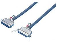
Centronics Connector Cable, High EMI Countermeasure Type (With DDK Connector)
Cable that converts sound energy into heat is used
- Printer
- EMI Countermeasure
- Solder
- Gold Plated
- Double Shield

● Cables that feature the Centronics connector that can be used for the connection of various control devices. Features two models of cables: the noiseBEAT cable that reduces noise by heat conversion, and the pair-shielded twisted pair cable that is aluminum foil coated.

· The noiseBEAT cable is a registered trademark of NTT Advanced Technology Corporation.
· The temperature increase by the heat conversion of the noise is roughly 0.1°C.
· Sheath peeling length can be designated as alteration service only for those with terminals or mark tubes.
· Specifying the length of the connector side ground cable is not supported.
· The shield is connected to the hood.
Wiring and Wire Color Page
>>Click here
Component Page
>>Click here
Part Number
Configured Part Number is shown.
Specifications
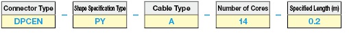
| Connector Type | Shape Specification Type | Outline Image Drawing (Unit: mm) | Cable Type | Number of Cores | Specified Length (m) |
| DPCEN EMI Countermeasure Type Solder Connector Spring Lock Type DDK | P (Male) |  |   | 14 | 0.2 ~ 50 |
| 24 | |||||
| JS (Female for Relay) |  | 14 | |||
| 24 | |||||
| PP (Male / Male) |  | 14 | |||
| 24 | |||||
| JSJS (Female for Relay / Female for Relay) |  | 14 | |||
| 24 | |||||
| PJS (Male / Female for Relay) |  | 14 | Can be specified by 0.1m increments | ||
| 24 | |||||
| PY (Male / Y Terminal F0.3-3 equivalent product) With Pin No. Insertion Mark Tube |  | 14 | |||
| 24 | |||||
| JSY (Female for Relay / Y Terminal F0.3-3 equivalent product) With Pin No. Insertion Mark Tube |  | 14 | |||
| 24 | |||||
| PT (Male Terminal / Loose Wires) With Pin No. Insertion Mark Tube |  | 14 | |||
| 24 | |||||
| JST (Female Terminal for Relay / Loose Wires) With Pin No. Insertion Mark Tube |  | 14 | |||
| 24 |
More Information
| L (m) | ~ 0.9 | 1 ~ 4 | 4.1 ~ 50 |
| Tolerance | +20mm | +50mm | + 3% of Total Length |
| Part Number |
|---|
| DPCEN-JS-B-14-[0.2-50/0.1] |
| DPCEN-JS-B-24-[0.2-50/0.1] |
| DPCEN-JSJS-B-14-[0.2-50/0.1] |
| DPCEN-JSJS-B-24-[0.2-50/0.1] |
| DPCEN-JST-B-14-[0.2-50/0.1] |
| DPCEN-JST-B-24-[0.2-50/0.1] |
| DPCEN-JSY-B-14-[0.2-50/0.1] |
| DPCEN-JSY-B-24-[0.2-50/0.1] |
| DPCEN-P-B-14-[0.2-50/0.1] |
| DPCEN-P-B-24-[0.2-50/0.1] |
| DPCEN-PJS-B-14-[0.2-50/0.1] |
| DPCEN-PJS-B-24-[0.2-50/0.1] |
| DPCEN-PP-B-14-[0.2-50/0.1] |
| DPCEN-PP-B-24-[0.2-50/0.1] |
| DPCEN-PT-B-14-[0.2-50/0.1] |
| DPCEN-PT-B-24-[0.2-50/0.1] |
| DPCEN-PY-B-14-[0.2-50/0.1] |
| DPCEN-PY-B-24-[0.2-50/0.1] |
| Part Number | Standard Unit Price | Minimum order quantity | Volume Discount | Days to Ship | CN1 | CN2 | Number Of Cores | Specified Length (m) |
|---|---|---|---|---|---|---|---|---|
- | 1 Piece(s) | 10 Day(s) or more | Female | Cut off | 14 | 0.2 ~ 50 | ||
- | 1 Piece(s) | 10 Day(s) or more | Female | Cut off | 24 | 0.2 ~ 50 | ||
- | 1 Piece(s) | 10 Day(s) or more | Female | Female | 14 | 0.2 ~ 50 | ||
- | 1 Piece(s) | 10 Day(s) or more | Female | Female | 24 | 0.2 ~ 50 | ||
- | 1 Piece(s) | 10 Day(s) or more | Female | Discrete wire | 14 | 0.2 ~ 50 | ||
- | 1 Piece(s) | 10 Day(s) or more | Female | Discrete wire | 24 | 0.2 ~ 50 | ||
- | 1 Piece(s) | 10 Day(s) or more | Female | Y terminal | 14 | 0.2 ~ 50 | ||
- | 1 Piece(s) | 10 Day(s) or more | Female | Y terminal | 24 | 0.2 ~ 50 | ||
- | 1 Piece(s) | 5 Day(s) or more | Male | Cut off | 14 | 0.2 ~ 50 | ||
- | 1 Piece(s) | 5 Day(s) or more | Male | Cut off | 24 | 0.2 ~ 50 | ||
- | 1 Piece(s) | 10 Day(s) or more | Male | Female | 14 | 0.2 ~ 50 | ||
- | 1 Piece(s) | 10 Day(s) or more | Male | Female | 24 | 0.2 ~ 50 | ||
- | 1 Piece(s) | 5 Day(s) or more | Male | Male | 14 | 0.2 ~ 50 | ||
- | 1 Piece(s) | 5 Day(s) or more | Male | Male | 24 | 0.2 ~ 50 | ||
- | 1 Piece(s) | 10 Day(s) or more | Male | Discrete wire | 14 | 0.2 ~ 50 | ||
- | 1 Piece(s) | 10 Day(s) or more | Male | Discrete wire | 24 | 0.2 ~ 50 | ||
- | 1 Piece(s) | 10 Day(s) or more | Male | Y terminal | 14 | 0.2 ~ 50 | ||
- | 1 Piece(s) | 10 Day(s) or more | Male | Y terminal | 24 | 0.2 ~ 50 |
Loading...
Material / Finish
| Item | Materials | Finish |
|---|---|---|
| Insulator (RC Type) | Glass-Filled Polybutylene Terephthalate |
UL94V-0, Blue |
| Insulator (Type 57, Angle Type) | DAP Resin | UL94V-0, Blue |
| Contact | Copper Alloy | Nickel Base Gold Plating |
| Shell | Steel | Nickel-plated |
| Hood (Angle Type Only) | Aluminum Alloy | Rustproofing Treatment |
| Spring Latch | Stainless Steel | - |

| Item | Materials | Finish |
|---|---|---|
| Insulator | PC Resin | UL94V-0, Blue |
| Contact | Copper Alloy | Nickel Base Gold Plating |
| Shell (57FE-40 only) |
Brass | Nickel-plated |
| Strain Relief | PC Resin | UL94V-0, Blue |
| Earth Plate (57FE-30 only) |
Brass | Nickel-plated |
| Spring Latch (57FE-40 only) |
Stainless Steel | - |
| Metal Hood (57FE-30 only) |
Aluminum Alloy | Rustproofing Treatment |

* 57F series is made up of 4 components: insulator, contact, strain relief, and pressure welding cover.
Compatible Wire
| Connector Type | Single Wire Conductor Diameter | Stranded Wire Conductor Cross-sectional Area | AWG Size |
|---|---|---|---|
| Soldering Type | 0.65 mm or less | 0.2 mm2 or less | Stranded Wire AWG24 or less Single Wire AWG22 or less |
| Pressure Welding Type | - | - | AWG26 (Single Wire), AWG28 (Stranded Wire, Single Wire) or AWG30 (Single Wire) 1.27 mm Pitch Flat Cable |
Electrical Properties
| Item | Soldering Type | Pressure Welding Type |
|---|---|---|
| Rated Current | 5 A or lower | 1 A or lower |
| Rated Voltage | 500 VAC or less | 250 VAC or less |
| Contact Resistance | 35 mΩ or less / 1 ADC | 35 mΩ or less / 1 ADC |
| Insulation Resistance | 1,000 MΩ or more / 500 VDC | 1,000 MΩ or more / 500 VDC |
| Withstand Voltage | 1,000 VAC / minute | 500 VAC / minute |
| Operating Temperature Range | -55°C ~ +105°C | -55°C ~ +105°C |
Mechanical Properties
| Item | Characteristics | Conditions |
|---|---|---|
| Insertion and Extraction Force Per Single Pole | Insertion Force: 112 g or less, Extraction Force: 86 g or less | When the plug and socket are inserted and extracted, the total extraction force is divided by each core number to convert into force per single pole |
| Vibration Resistance | · No interruption to power supplies of 1 μs or more · No abnormalities such as damage etc. on the connector |
In compliance with MIL-STD-202 test method condition 204 A, simple vibration with smaller amplitude, either the total amplitude of 1.52 mm from 10 Hz to 500 Hz or 10 G (gravity units) is applied to each for 3 hours in mutually perpendicular 3-axis direction. |
| Impact Resistance | No cracks in the connector or abnormalities such as loosening in breakable parts | Impact of 50 G with duration 11 msec is applied to the coupled connector in mutually perpendicular axis direction. |
| Insertion and Removal Durability | No mechanical damage | Perform insertion and removal 500 times at speeds not exceeding 500 times per 1 hour. |
Environmental Properties
| Item | Characteristics | Conditions |
|---|---|---|
| Temperature Resistance | There should be no physical damage or obstacle when inserting or removing the connector | Repeatedly expose to temperatures +85°C and -55°C for 30 minutes 5 times each. However, do not expose to room temperature for 5 minutes or more when moving from low temperature to high and from high temperature to low. |
| Humidity Resistance | · There should be no mechanical damages · Voltage Resistance 300 VAC 1 minute |
Perform 96-hour humidity test with the connector detached in compliance with MIL-STD-202 test method 103 B. |
| Corrosion Resistance | There should be no significant corrosion or obstacle when inserting or removing the connector | After performing a 48-hour salt spray test with the connector attached in compliance with MIL-STD-202 test method condition 101 B, the connector is uncoupled, washed, and dried for 12 hours in a drying oven at 38°C. |
Contact Arrangement Diagram

This diagram is a view of the socket (female) connector from the coupling.
The plug (male) will be reversed on the left and right.
Basic Information
| Connector type | Centronics | Connector manufacturer | DDK Ltd. | Connector Shape | Straight |
|---|---|---|---|---|---|
| Machining Method | Solder | Cable shape | Circular | Hood | EMI-compatible metal |
| Cable rated voltage(V) | Less than 100 | Shield | Aluminum Foil + Braided Pair Double / Each Pair Aluminum Foil | Cable standard (UL/CSA) | UL |
| Cable color | Navy | Twisted pair | Included | AWG | 25 |
| Cable type | B | Connector fastening method | Spring-lock |
- The specifications and dimensions of some parts may not be fully covered. For exact details, refer to manufacturer catalogs .
Tech Support
- Factory Automation, Electronics, Tools, & MRO (Maintenance, Repair and Operations)
- Tel:(65) 6733 7211 / FAX:(65) 6733 0211
- 9:00am - 6:00pm (Monday - Friday)
- Technical Inquiry
Payment Method
- Credit Card
- PayPal
- Bank Transfer
Social Media
MISUMI Contact
Copyright © MISUMI Corporation All Rights Reserved.
How can we improve?
How can we improve?