(!)Due to Microsoft's end of support for Internet Explorer 11 on 15/06/2022, this site does not support the recommended environment.
Instead, please kindly use other browsers like Google Chrome, Microsoft Edge or Mozilla Firefox.
50,000 Stock items for Same Day Ship Out.
All Categories
Categories
- Automation Components
A wide variety of standard and configurable components for factory automation engineers in industries such as automotive, semiconductor, packaging, medical and many more.
- Linear Motion
- Rotary Motion
- Connecting Parts
- Rotary Power Transmission
- Motors
- Conveyors & Material Handling
- Locating, Positioning, Jigs & Fixtures
- Inspection
- Sensors, Switches
- Pneumatics, Hydraulics
- Vacuum Components
- Hydraulic Equipment
- Discharging / Painting Devices
- Pipe, Tubes, Hoses & Fittings
- Modules, Units
- Heaters, Temperature Control
- Framing & Support
- Casters, Leveling Mounts, Posts
- Doors, Cabinet Hardware
- Springs, Shock Absorbers
- Adjusting, Fastening, Magnets
- Antivibration, Soundproofing Materials, Safety Products
- Fasteners
A good selection of accessories such as screws, bolts, washers and nuts that you may need for your daily engineering usage.
- Materials
Browse industrial materials ranging from heat insulating plates, sponges, to metal and plastic materials in different sizes to meet your various applications.
- Wiring Components
A wide variety of wiring parts for connecting and protecting control and PC parts including Connectors, Cables, Electric Wires, Crimping Terminals and more.
- LAN Cables / Industrial Network Cables
- Cables by Application
- Cables with Connectors
- RS232 / Personal Computers / AV Cables
- Wires/Cables
- Connectors (General Purpose)
- Crimp Terminals
- Zip Ties
- Cable Glands
- Cable Bushings/Clips/Stickers
- Screws/Spacers
- Cable Accessories
- Tubes
- Protection Tubes
- Ducts/Wiremolds
- General Purpose Tools
- Dedicated Tools
- Soldering Supplies
- Electrical & Controls
A wide variety of controls and PC parts for electrical engineers including Controls, Powers, PC parts and more.
- Cutting Tools
A wide variety of cutting tools for many uses and work materials including End Mills, Drills, Cutters, Reamers, Turning Tools and more.
- Carbide End Mills
- HSS End Mills
- Milling Cutter Inserts/Holders
- Customized Straight Blade End Mills
- Dedicated Cutters
- Turning Tools
- Drill Bits
- Screw-Hole-Related Tools
- Reamers
- Chamfering / Centering Tools
- Fixtures Related to Cutting Tools
- Step Drills
- Hole Saws
- Clean Key Cutters
- Core Drills (Tip Tools)
- Magnetic Drilling Machine Cutters
- Drill Bits for Electric Drilling Machines
- Woodworking Drill Cutters
- Drills for Concrete
- Processing Tools
A wide variety of tools and supplies used in processing including Machine Tools, Measurement Tools, Grinding and Polishing Supplies and more.
- Material Handling & Storage
A wide variety of goods used in shipment, material handling and warehouse including Tape supplies, Stretch film, Truck, Shelf, Crane and more.
- Tape Supplies
- Cushioning Materials
- Stretch Films
- Cardboard
- Plastic Bags
- PP Bands
- Magic Tapes / Tying Belts
- Rubber Bands
- Strings/Ropes
- Cable Ties
- Tags
- Labelers
- Unpacking Cutters
- Packing Support Equipment
- Cloth Sheets for Packing
- Conveyance/Dolly Carts
- Tool Wagons
- Tool Cabinets / Container Racks
- Lifters / Hand Pallets
- Container Pallets
- Storage Supplies
- Shelves/Racks
- Work Benches
- Suspended Clamps/Suspended Belts
- Jack Winches
- Chain Block Cranes
- Bottles/Containers
- Bicycle Storage Area
- Safety & General Supplies
A large variety of goods for every kind of factories and offices including Protection items, Cleaning supplies, sanitations, office supplies and more.
- Lab & Clean Room Supplies
A large variety of items used in R&D and Clean Room including research Equipment, Laboratory Essentials, Analysis Supplies, Clean Environment-Related Equipment and more.
- Press Die Components
Choose from thousands of standard stamping die components including Punch & Die, Gas Springs, Guide Components, Coil Springs and many more.
- Plastic Mold Components
Browse our wide variety of mold components including Ejector Pins, Sleeves, Leader Components, Sprue Bushings and many more.
- Ejector Pins
- Sleeves, Center Pins
- Core Pins
- Sprue bushings, Gates, and other components
- Date Mark Inserts, Recycle Mark Inserts, Pins with Gas Vent
- Undercut, Plates
- Leader Components, Components for Ejector Space
- Mold Opening Controllers
- Cooling or Heating Components
- Accessories, Others
- Components of Large Mold, Die Casting
- Injection Molding Components
Browse our injection molding components including Heating Items, Couplers, Hoses and more.
- Injection Molding Machine Products
- Accessories of Equipment
- Auxiliary Equipment
- Air Nippers
- Air Cylinders
- Air Chuck for Runner
- Chuck Board Components
- Frames
- Suction Components
- Parallel Air Chuck
- Special Air Chuck
- Chemical for Injection Molding
- Mold Maintenance
- Heating Items
- Heat Insulation Sheets
- Couplers, Plugs, One-touch Joints
- Tubes, Hoses, Peripheral Components
Search by Application
Brands


- Please be informed that our office is closed during the upcoming Labour Day Holiday in 2024. We would also like to inform you that there may be a potential delay in response/shipment from the supplier due to the Japan Golden Week holiday which falls from 29th April to 6th May 2024. Click here for details.
- Please Note our New Address (effective April 1, 2024): 331 North Bridge Rd, #05-01 Odeon 331, Singapore 188720.
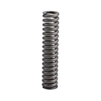
Compression Spring - O.D. Referenced Stainless Steel, Extra Light Load [RoHS Comliant]
![Compression Spring - O.D. Referenced Stainless Steel, Extra Light Load [RoHS Comliant]](http://content.misumi-ec.com/image/upload/t_product_main/t_misumi_wm/v1/p/cn/product/series/110310295109/110310295109_20200521163939.jpg?$product_main$)
![Compression Spring - O.D. Referenced Stainless Steel, Extra Light Load [RoHS Comliant]](http://content.misumi-ec.com/image/upload/t_product_thum/t_misumi_wm/v1/p/cn/product/series/110310295109/110310295109_20200521163939.jpg?$product_thum$)
![Compression Spring - O.D. Referenced Stainless Steel, Extra Light Load [RoHS Comliant]](http://content.misumi-ec.com/image/upload/t_product_thum/t_misumi_wm/v1/p/cn/product/series/110310295109/110310295109_20200521163940.jpg?$product_thum$)
![Compression Spring - O.D. Referenced Stainless Steel, Extra Light Load [RoHS Comliant]](http://content.misumi-ec.com/image/upload/t_product_thum/t_misumi_wm/v1/p/cn/product/series/110310295109/110310295109_20200521163941.jpg?$product_thum$)
- Volume Discount
\RoHS10-compliant products are newly released.
(i)Caution
- This product can be purchased in quantities of 10pcs. Please enter your order quantity in multiples of 10. * Minimum order quantity (10 pcs. or more)
- Since it is an O.D. referenced type spring, it is manufactured with priority given to O.D. tolerances. Please be careful.
- Stainless Steel Spring is magnetic.
Part Number
Configured Part Number is shown.
E-GUF20-25
Dimensional Drawing of Compression Springs
 0-0.5 mm0-0.8 mm
| O.D. D | ø10 or Less | Free Length L | ±1.5 mm | ||
| ø12 or More | Spring Constant | ±10% |
Specification Table of Compression Springs
[ ! ] Compression Springs O.D. Referenced Type is outer diameter prioritized, and the I.D. is a reference value.
| Part Number | d | I.D. D-2d | Solid Length | F | N (kgf) | Fa% | Total Coils | Number of active coils | ||
| TYPE D-L | (reference value) | (reference value) | max. | max. | (reference value) | (reference value) | ||||
| E-GUV 3- | 5* | 0.15 | 2.7 | 1.1 | 4 | 0.18 | {0.018} | 70 | 6 | 4 |
| 10* | 0.18 | 2.64 | 2.5 | 7 | 0.35 | {0.036} | 12.8 | 10.8 | ||
| 15* | 0.18 | 2.64 | 2.5 | 11 | 0.53 | {0.054} | 12.8 | 10.8 | ||
| E-GUV 4- | 5* | 0.18 | 3.64 | 1.2 | 4 | 0.18 | {0.018} | 5.6 | 3.6 | |
| 10* | 0.2 | 3.6 | 1.7 | 7 | 0.35 | {0.036} | 7.5 | 5.5 | ||
| 15* | 0.23 | 3.54 | 3 | 11 | 0.53 | {0.054} | 12 | 10 | ||
| 20* | 0.23 | 3.54 | 3 | 14 | 0.7 | {0.071} | 12 | 10 | ||
| E-GUV 5- | 10* | 0.23 | 4.54 | 1.8 | 7 | 0.35 | {0.036} | 6.8 | 4.8 | |
| 15* | 0.26 | 4.48 | 2.9 | 11 | 0.53 | {0.054} | 10.1 | 8.1 | ||
| 20* | 0.29 | 4.42 | 4.5 | 14 | 0.7 | {0.071} | 14.5 | 12.5 | ||
| E-GUV 6- | 10* | 0.26 | 5.48 | 2 | 7 | 0.35 | {0.036} | 6.6 | 4.6 | |
| 15* | 0.3 | 5.4 | 3.3 | 11 | 0.53 | {0.054} | 10 | 8 | ||
| E-GUV 8- | 10* | 0.3 | 7.4 | 1.9 | 7 | 0.35 | {0.036} | 5.3 | 3.3 | |
| 15* | 0.35 | 7.3 | 3.2 | 11 | 0.53 | {0.054} | 8.1 | 6.1 | ||
| 20* | 0.35 | 7.3 | 3.2 | 14 | 0.7 | {0.071} | 8.1 | 6.1 | ||
| 25* | 0.4 | 7.2 | 5.6 | 18 | 0.88 | {0.089} | 13 | 11 | ||
| 40* | 0.45 | 7.1 | 9.3 | 28 | 1.4 | {0.143} | 19.6 | 17.6 | ||
● How to Determine the Number of Winding (reference value):
Total coils = solid length / wire diameter (d) - 1
Number of active coils = total coils - 2
* The values of the number of coils are for reference only. There may be some variations depending on the lot.
[!] The values of solid length are for reference only. There may be some variations depending on the lot.
Using it compressed to the solid length may cause deformation or break after a few uses.
[ ! ] Be sure to use the Compression Springs within the range of the allowable deflection F max.(mm).
[ ! ] O.D. Referenced Type is outer diameter prioritized, and the I.D. is a reference value.
| Part Number | d | I.D. D-2d | Solid Length | F | N (kgf) | Fa% | Total Coils | Number of active coils | ||
| TYPE D-L | (reference value) | (reference value) | max. | max. | (reference value) | (reference value) | ||||
| E-GUY 2- | 5* | 0.13 | 1.74 | 1.5 | 3 | 0.15 | {0.015 } | 60 | 11 | 9 |
| 10* | 0.13 | 1.74 | 1.5 | 6 | 0.29 | {0.03 } | 10.5 | 8.5 | ||
| 15* | 0.15 | 1.7 | 2.7 | 9 | 0.44 | {0.045 } | 17 | 15 | ||
| E-GUY 3- | 10* | 0.2 | 2.6 | 2 | 7.5 | 0.74 | {0.075 } | 75 | 9 | 7 |
| 15* | 0.23 | 2.54 | 3.45 | 11.25 | 1.1 | {0.1125} | 14 | 12 | ||
| E-GUY 4- | 5* | 0.2 | 3.6 | 1.05 | 3.75 | 0.37 | {0.0375} | 75 | 4.2 | 2.2 |
| 10* | 0.23 | 3.54 | 1.84 | 7.5 | 0.74 | {0.075 } | 7 | 5 | ||
| 15* | 0.26 | 3.48 | 2.86 | 11.25 | 1.1 | {0.1125} | 10 | 8 | ||
| 20* | 0.29 | 3.42 | 4.64 | 15 | 1.47 | {0.15 } | 15 | 13 | ||
| 25* | 0.3 | 3.4 | 5.4 | 18.75 | 1.84 | {0.1875} | 17 | 15 | ||
| 30* | 0.3 | 3.4 | 5.4 | 22.5 | 2.26 | {0.23 } | 17 | 15 | ||
| E-GUY 5- | 10* | 0.26 | 4.48 | 1.82 | 7.5 | 0.74 | {0.075 } | 75 | 6 | 4 |
| 15* | 0.3 | 4.4 | 3.15 | 11.25 | 1.1 | {0.1125} | 9.5 | 7.5 | ||
| 20* | 0.3 | 4.4 | 3.15 | 15 | 1.47 | {0.15 } | 9.5 | 7.5 | ||
| 25* | 0.32 | 4.36 | 4.16 | 18.75 | 1.84 | {0.1875} | 12 | 10 | ||
| E-GUY 6- | 5* | 0.26 | 5.48 | 1.24 | 3.5 | 0.34 | {0.035 } | 70 | 3.7 | 1.7 |
| 10* | 0.3 | 5.4 | 2.1 | 7.5 | 0.74 | {0.075 } | 75 | 6 | 4 | |
| 15* | 0.32 | 5.36 | 2.64 | 11.25 | 1.1 | {0.1125} | 7.2 | 5.2 | ||
| 20* | 0.35 | 5.3 | 3.85 | 15 | 1.47 | {0.15 } | 10 | 8 | ||
| 25* | 0.38 | 5.24 | 5.32 | 18.75 | 1.84 | {0.1875} | 13 | 11 | ||
| 30* | 0.4 | 5.2 | 6.8 | 22.5 | 2.21 | {0.225 } | 16 | 14 | ||
| E-GUY 8- | 10* | 0.35 | 7.3 | 2.19 | 7.5 | 0.74 | {0.075 } | 75 | 5.2 | 3.2 |
| 15* | 0.4 | 7.2 | 3.4 | 11.25 | 1.1 | {0.1125} | 7.5 | 5.5 | ||
| 20* | 0.4 | 7.2 | 3.4 | 15 | 1.47 | {0.15 } | 7.5 | 5.5 | ||
| 25* | 0.45 | 7.1 | 5.4 | 18.75 | 1.84 | {0.1875} | 11 | 9 | ||
| 30* | 0.45 | 7.1 | 5.4 | 22.5 | 2.21 | {0.225 } | 11 | 9 | ||
| E-GUY 10- | 15* | 0.5 | 9 | 3.25 | 11.25 | 2.21 | {0.225 } | 75 | 5.5 | 3.5 |
| 20* | 0.55 | 8.9 | 4.4 | 15 | 2.94 | {0.3 } | 7 | 5 | ||
| 25* | 0.55 | 8.9 | 4.4 | 18.75 | 3.68 | {0.375 } | 7 | 5 | ||
| 30* | 0.6 | 8.8 | 6.15 | 22.5 | 4.41 | {0.45 } | 9.2 | 7.2 | ||
| 35* | 0.6 | 8.8 | 6.3 | 26.25 | 5.1 | {0.52 } | 9.5 | 7.5 | ||
| E-GUY 12- | 15* | 0.55 | 10.9 | 3.3 | 11.25 | 2.206 | {0.225 } | 75 | 5 | 3 |
● How to Determine the Number of Winding (reference value):
Total coils = solid length / wire diameter (d) - 1
Number of active coils = total coils - 2
* The values of the number of coils are for reference only. There may be some variations depending on the lot.
[!] The values of solid length are for reference only. There may be some variations depending on the lot.
Using it compressed to the solid length may cause deformation or break after a few uses.
[ ! ] Be sure to use the Compression Springs within the range of the allowable deflection F max.(mm).
[ ! ] O.D. Referenced Type is outer diameter prioritized, and the I.D. is a reference value.
| Part Number | d | I.D. D-2d | Solid Length | F | N (kgf) | Fa% | Total Coils | Number of active coils | ||
| TYPE D-L | (reference value) | (reference value) | max. | max. | (reference value) | (reference value) | ||||
| E-GUR 2- | 5* | 0.18 | 1.64 | 2 | 2.5 | 0.49 | {0.05} | 50 | 10 | 8 |
| 10* | 0.18 | 1.64 | 2 | 5 | 0.98 | {0.1 } | 10 | 8 | ||
| 15* | 0.23 | 1.54 | 6 | 7.5 | 1.5 | {0.15} | 25 | 23 | ||
| E-GUR 3- | 5* | 0.23 | 2.54 | 1.6 | 3 | 0.9 | {0.09} | 60 | 5 | 3 |
| 10* | 0.25 | 2.5 | 2.1 | 6 | 1.8 | {0.18} | 7 | 5 | ||
| 15* | 0.3 | 2.4 | 4.5 | 9 | 2.6 | {0.27} | 14 | 12 | ||
| 20* | 0.3 | 2.4 | 4.5 | 12 | 3.5 | {0.36} | 14 | 12 | ||
| 25* | 0.32 | 2.36 | 6.4 | 15 | 4.4 | {0.45} | 19 | 17 | ||
| E-GUR 4- | 5* | 0.26 | 3.48 | 1.4 | 3 | 0.9 | {0.09} | 60 | 4 | 2 |
| 10* | 0.29 | 3.42 | 2 | 6 | 1.8 | {0.18} | 5 | 3 | ||
| 15* | 0.32 | 3.36 | 3 | 9 | 2.6 | {0.27} | 8 | 6 | ||
| 20* | 0.38 | 3.24 | 6.1 | 12 | 3.5 | {0.36} | 15 | 13 | ||
| 25* | 0.38 | 3.24 | 6.1 | 15 | 4.4 | {0.45} | 15 | 13 | ||
| 30* | 0.4 | 3.2 | 8 | 18 | 5.3 | {0.54} | 19 | 17 | ||
| E-GUR 5- | 10* | 0.35 | 4.3 | 2.71 | 6 | 1.8 | {0.18} | 60 | 6 | 4 |
| 15* | 0.38 | 4.24 | 3.61 | 9 | 2.6 | {0.27} | 8 | 6 | ||
| 20* | 0.38 | 4.24 | 3.61 | 12 | 3.5 | {0.36} | 8 | 6 | ||
| 25* | 0.45 | 4.1 | 7.43 | 15 | 4.4 | {0.45} | 15 | 13 | ||
| 30* | 0.45 | 4.1 | 7.43 | 18 | 5.3 | {0.54} | 15 | 13 | ||
| 35* | 0.5 | 4 | 12.25 | 21 | 6.2 | {0.63} | 23 | 21 | ||
| E-GUR 6- | 5* | 0.32 | 5.36 | 1.5 | 3 | 0.9 | {0.09} | 60 | 3 | 1 |
| 10* | 0.4 | 5.2 | 3 | 6 | 1.8 | {0.18} | 6 | 4 | ||
| 15* | 0.4 | 5.2 | 3 | 9 | 2.6 | {0.27} | 6 | 4 | ||
| 20* | 0.5 | 5 | 7 | 12 | 3.5 | {0.36} | 13 | 11 | ||
| 25* | 0.5 | 5 | 7 | 15 | 4.4 | {0.45} | 13 | 11 | ||
| 30* | 0.5 | 5 | 7 | 18 | 5.3 | {0.54} | 13 | 11 | ||
| E-GUR 8- | 10* | 0.45 | 7.1 | 2.6 | 6 | 1.8 | {0.18} | 60 | 4 | 2 |
| 15* | 0.5 | 7 | 3.6 | 9 | 2.6 | {0.27} | 6 | 4 | ||
| 20* | 0.5 | 7 | 3.6 | 12 | 3.5 | {0.36} | 6 | 4 | ||
| 25* | 0.55 | 6.9 | 5.9 | 15 | 4.4 | {0.45} | 9 | 7 | ||
| 30* | 0.65 | 6.7 | 10.4 | 18 | 5.3 | {0.54} | 15 | 13 | ||
| 35* | 0.65 | 6.7 | 10.4 | 21 | 6.2 | {0.63} | 15 | 13 | ||
| E-GUR 10- | 10* | 0.55 | 8.9 | 3.3 | 6 | 1.8 | {0.18} | 60 | 5 | 3 |
| 15* | 0.6 | 8.8 | 4.2 | 9 | 2.6 | {0.27} | 6 | 4 | ||
| 20* | 0.65 | 8.7 | 6.2 | 12 | 3.5 | {0.36} | 8 | 6 | ||
| 25* | 0.65 | 8.7 | 6.2 | 15 | 4.4 | {0.45} | 8 | 6 | ||
| 30* | 0.7 | 8.6 | 8.4 | 18 | 5.3 | {0.54} | 11 | 9 | ||
● How to Determine the Number of Winding (reference value):
Total coils = solid length / wire diameter (d) - 1
Number of active coils = total coils - 2
* The values of the number of coils are for reference only. There may be some variations depending on the lot.
[!] The values of solid length are for reference only. There may be some variations depending on the lot.
Using it compressed to the solid length may cause deformation or break after a few uses.
[ ! ] Be sure to use the Compression Springs within the range of the allowable deflection F max.(mm).
[ ! ] O.D. Referenced Type is outer diameter prioritized, and the I.D. is a reference value.
| Part Number | d | I.D. D-2d | Solid Length | F | N (kgf) | Fa% | Total Coils | Number of active coils | ||
| TYPE D-L | (reference value) | (reference value) | max. | max. | (reference value) | (reference value) | ||||
| E-GUF 2- | 5* | 0.2 | 1.6 | 2.35 | 2.25 | 0.66 | {0.068} | 45 | 10 | 8 |
| 10* | 0.2 | 1.6 | 2.35 | 4.5 | 1.3 | {0.14 } | 10 | 8 | ||
| E-GUF 3- | 5* | 0.26 | 2.48 | 1.8 | 2.25 | 1.1 | {0.11 } | 5 | 3 | |
| 10* | 0.32 | 2.36 | 4.5 | 4.5 | 2.2 | {0.22 } | 13 | 11 | ||
| 15* | 0.32 | 2.36 | 4.5 | 6.7 | 3.2 | {0.33 } | 13 | 11 | ||
| 20* | 0.35 | 2.3 | 6.3 | 9 | 4.4 | {0.45 } | 17 | 15 | ||
| 25* | 0.35 | 2.3 | 6.3 | 11.2 | 5.5 | {0.56 } | 17 | 15 | ||
| E-GUF 4- | 5* | 0.32 | 3.36 | 2 | 2.25 | 1.1 | {0.11 } | 5 | 3 | |
| 10* | 0.35 | 3.3 | 3 | 4.5 | 2.2 | {0.22 } | 7 | 5 | ||
| 15* | 0.4 | 3.2 | 5.2 | 6.7 | 3.2 | {0.33 } | 12 | 10 | ||
| 20* | 0.4 | 3.2 | 5.2 | 9 | 4.4 | {0.45 } | 12 | 10 | ||
| 25* | 0.45 | 3.1 | 9.5 | 11.2 | 5.5 | {0.56 } | 20 | 18 | ||
| 30* | 0.45 | 3.1 | 9.5 | 13.5 | 6.6 | {0.67 } | 20 | 18 | ||
| E-GUF 5- | 10* | 0.4 | 4.2 | 3.2 | 4.5 | 2.2 | {0.23 } | 7 | 5 | |
| 15* | 0.4 | 4.2 | 3.2 | 6.75 | 3.3 | {0.34 } | 7 | 5 | ||
| 20* | 0.45 | 4.1 | 4.95 | 9 | 4.4 | {0.45 } | 10 | 8 | ||
| 25* | 0.45 | 4.1 | 4.95 | 11.25 | 5.5 | {0.56 } | 10 | 8 | ||
| 30* | 0.5 | 4 | 7.75 | 13.5 | 6.7 | {0.68 } | 14 | 12 | ||
| 35* | 0.5 | 4 | 7.75 | 15.75 | 7.7 | {0.79 } | 14 | 12 | ||
| E-GUF 6- | 10* | 0.5 | 5 | 5 | 4.5 | 2.2 | {0.22 } | 9 | 7 | |
| 15* | 0.55 | 4.9 | 7.7 | 6.7 | 3.2 | {0.33 } | 13 | 11 | ||
| 20* | 0.55 | 4.9 | 7.7 | 9 | 4.4 | {0.45 } | 13 | 11 | ||
| 25 | 0.6 | 4.8 | 10.8 | 11.2 | 5.5 | {0.56 } | 17 | 15 | ||
| 30 | 0.65 | 4.7 | 15.6 | 13.5 | 6.6 | {0.67 } | 23 | 21 | ||
| E-GUF 8- | 10 | 0.6 | 6.8 | 5.4 | 4.5 | 2.2 | {0.22 } | 8 | 6 | |
| 15 | 0.65 | 6.7 | 7.2 | 6.7 | 3.2 | {0.33 } | 10 | 8 | ||
| 20 | 0.7 | 6.6 | 10.5 | 9 | 4.4 | {0.45 } | 14 | 12 | ||
| 25 | 0.7 | 6.6 | 10.5 | 11.2 | 5.5 | {0.56 } | 14 | 12 | ||
| 30 | 0.75 | 6.5 | 13.5 | 13.5 | 6.6 | {0.67 } | 17 | 15 | ||
| 35 | 0.75 | 6.5 | 13.5 | 15.7 | 7.6 | {0.78 } | 17 | 15 | ||
| E-GUF 10- | 15 | 0.65 | 8.7 | 4.6 | 6.7 | 3.2 | {0.33 } | 6 | 4 | |
| 20 | 0.8 | 8.4 | 9.6 | 9 | 4.4 | {0.45 } | 11 | 9 | ||
| 25 | 0.8 | 8.4 | 9.6 | 11.2 | 5.5 | {0.56 } | 11 | 9 | ||
| 30 | 0.85 | 8.3 | 12.8 | 13.5 | 6.6 | {0.67 } | 14 | 12 | ||
| E-GUF 12- | 20 | 0.8 | 10.4 | 6.8 | 9 | 4.4 | {0.45 } | 7 | 5 | |
| E-GUF 16- | 35 | 1.1 | 13.8 | 12.1 | 15.7 | 7.6 | {0.78 } | 10 | 8 | |
| E-GUF 20- | 25 | 1.3 | 17.4 | 9.1 | 11.3 | 11.1 | {1.13 } | 6 | 4 | |
(kgf) = N × 0.101972
● How to Determine the Number of Winding (reference value):
Total coils = solid length / wire diameter (d) - 1
Number of active coils = total coils - 2
* The values of the number of coils are for reference only. There may be some variations depending on the lot.
[!] The values of solid length are for reference only. There may be some variations depending on the lot.
Using it compressed to the solid length may cause deformation or break after a few uses.
[ ! ] Be sure to use the Compression Springs within the range of the allowable deflection F max.(mm).
| O.D. | O.D. Referenced | ||||||||
| D | E-GUV | E-GUY | E-GUR | E-GUF | E-GUL | E-GUTT | E-GUM | E-GUH | E-GUBB |
| 2 | 0.05 | 0.2 | 0.3 | 0.5 | |||||
| {0.005} | {0.02} | {0.03} | {0.05} | ||||||
| 3 | 0.05 {0.005} | 0.098 {0.01} | 0.29 {0.03} | 0.49 {0.05} | 0.98 {0.1} | 1.5 | |||
| 4 | {0.15} | 2 | 2.9 | 4.9 | |||||
| 5 | 2 {0.2} | {0.2} | {0.3} | {0.5} | |||||
| 6 | 2.9 {0.3} | 5.9 {0.6} | 9.8 {1.0} | ||||||
| 8 | |||||||||
| 10 | 0.2 | ||||||||
| 12 | {0.02} | ||||||||
| 13 | 2 | 2.9 | 9.8 | 19.6 | |||||
| {0.2} | {0.3} | {1.0} | {2.0} | ||||||
| 14 | |||||||||
| 16 | 0.49 {0.05} | 2 {0.2} | 19.6 | ||||||
| {2.0} | |||||||||
| 20 | 0.98 | 2.9 | 29.4 | ||||||
| {0.1} | {0.3} | {3.0} | |||||||
| Fmax. | F = | F = | F = | F = | F = | F = | F = | F = | F = |
| L × 70% | L × 75% | L × 60% | L × 45% | L × 40% | L × 40% | L × 35% | L × 30% | L × 25% | |
| I.D. | I.D. Referenced | |||
| D | E-GVUR | E-GVUF | E-GVUL | E-GVUM |
| 5 | 0.29 {0.03} | 0.49 {0.05} | 0.98 {0.10} | 2.94 {0.30} |
| 6 | ||||
| 8 | ||||
| 10 | ||||
| 12 | ||||
| 16 | 2.94 {0.30} | |||
| Fmax. | F= | F= | F= | F= |
| L × 60% | L × 45% | L × 40% | L × 35% | |
Related Products of Compression Springs
| [Economy Series / Large Quantity Order Super-Discount] Compression Springs O.D. Referenced Stainless Steel, Extra Light Load | [Economy Series / Large Quantity Order Super-Discount] Compression Springs O.D. Referenced Stainless Steel, Light Load | [Economy Series / Large Quantity Order Super-Discount] Compression Springs O.D. Referenced Stainless Steel, Heavy Load | ||
 | | | ||
| Type: E-GUF, E-GUR, E-GUV, E-GUY | Type: E-GUL, E-GUTT | Type: E-GUH, E-GUM | ||
| Standard Days to Ship: 1 Day (In Stock Products) | Standard Days to Ship: 1 Day (In Stock Products) | Standard Days to Ship: 1 Day (In Stock Products) | ||
| Unit Price: From 50 JPY | Unit Price: From 50 JPY | Unit Price: From 55 yen |
| [Economy Series / Large Quantity Order Super-Discount] Compression Springs O.D. Referenced Stainless Steel, Ultra Heavy Load | [Economy Series / Large Quantity Order Super-Discount] Compression Springs I.D. Referenced Stainless Steel, Light Load | [Economy Series / Large Quantity Order Super-Discount] Compression Springs I.D. Referenced Stainless Steel, Heavy Load | ||
 | | | ||
| Type: E-GUBB | Type: E-GVUF, E-GVUR | Type: E-GVUL, E-GVUM | ||
| Standard Days to Ship: 1 Day (In Stock Products) | Standard Days to Ship: 1 Day (In Stock Products) | Standard Days to Ship: 1 Day (In Stock Products) | ||
| Unit Price: From 105 yen | Unit Price: From 85 yen | Unit Price: From 95 yen |
Part Number
CAD Data download and 3D preview are not available because the part number has not yet been determined.
- *In order to open the CAD Data download and 3D preview screen, the part number must be fixed.
- Please confirm the part number from "Specification / Dimension"on the left side, and then perform the CAD Data Download / 3D Preview operation.
| Part Number |
|---|
| E-GUF20-25 |
| Part Number | Standard Unit Price | Minimum order quantity | Volume Discount | Days to Ship | RoHS | Free Length L (mm) | Outer Dia. D (or D1) (Ø) | Spring Constant (N/mm) | Allowable Load (Configurable Range) (N) | Max. Load (N) | Wire Dia. (Ø) | Solid Length (mm) | Allowable Displacement (mm) | End Face State | Maximum Height when Loaded (Free Length, Allowable Deflection) (mm) | I.D. D (⌀) (φ) | Total Coils Nt *Reference Value |
|---|---|---|---|---|---|---|---|---|---|---|---|---|---|---|---|---|---|
SGD 1.14 | 10 Piece(s) | Available | 4 Day(s) or more | 10 | 25 | 20 | 0.98 | 8.51~16.00 | 11.1 | 1.3 | 9.1 | 11.3 | With grinding | 13.7 | 17.4 | 6 |
Loading...
Precautions
Cautions on UseOperating Temperature
Stainless Steel:: -10 to 100°C
* Load value attenuates when tension springs are used in temperature higher than above, although it depends on other conditions.
Stainless Steel Spring is magnetic.
Basic Information
| Material | SUS304-WPB |
|---|
Please check the type/dimensions/specifications of the part E-GUF20-25 in the Compression Spring - O.D. Referenced Stainless Steel, Extra Light Load [RoHS Comliant] series.
Specification/Dimensions
-
Free Length L(mm)
-
Outer Dia. D (or D1)(Ø)
-
Spring Constant(N/mm)
-
Max. Load(N)
-
Wire Dia.(Ø)
-
Solid Length(mm)
- 1.05
- 1.1
- 1.2
- 1.24
- 1.4
- 1.5
- 1.6
- 1.7
- 1.8
- 1.82
- 1.84
- 1.9
- 2
- 2.1
- 2.19
- 2.35
- 2.5
- 2.6
- 2.64
- 2.7
- 2.71
- 2.86
- 2.9
- 3
- 3.15
- 3.2
- 3.25
- 3.3
- 3.4
- 3.45
- 3.6
- 3.61
- 3.85
- 4.16
- 4.2
- 4.4
- 4.5
- 4.6
- 4.64
- 4.95
- 5
- 5.2
- 5.32
- 5.4
- 5.6
- 5.9
- 6
- 6.1
- 6.15
- 6.2
- 6.3
- 6.4
- 6.8
- 7
- 7.2
- 7.43
- 7.7
- 7.75
- 8
- 8.4
- 9.1
- 9.3
- 9.5
- 9.6
- 10.4
- 10.5
- 10.8
- 12.1
- 12.25
- 12.8
- 13.5
- 15.6
-
Allowable Displacement(mm)
-
End Face State
- No grinding
- With grinding
-
Maximum Height when Loaded (Free Length, Allowable Deflection)(mm)
-
I.D. D (⌀)(φ)
-
Total Coils Nt *Reference Value
-
type
- E-GUF
- E-GUR
- E-GUV
- E-GUY
-
Allowable Load (Configurable Range)(N)
- ~1.50
- 1.51~4.50
- 4.51~8.50
- 8.51~16.00
-
CAD
- 2D
- 3D
Days to Ship
-
- All
- 4 Day(s) or Less
Specify Alterations
- The specifications and dimensions of some parts may not be fully covered. For exact details, refer to manufacturer catalogs .
Similar Part Numbers
| Part Number |
|---|
| E-GUF10-30 |
| E-GUF12-20 |
| E-GUF16-35 |
| E-GUF3-10 |
| E-GUF3-15 |
| E-GUF3-20 |
| Part Number | Standard Unit Price | Minimum order quantity | Volume Discount | Days to Ship | RoHS | Free Length L (mm) | Outer Dia. D (or D1) (Ø) | Spring Constant (N/mm) | Allowable Load (Configurable Range) (N) | Max. Load (N) | Wire Dia. (Ø) | Solid Length (mm) | Allowable Displacement (mm) | End Face State | Maximum Height when Loaded (Free Length, Allowable Deflection) (mm) | I.D. D (⌀) (φ) | Total Coils Nt *Reference Value |
|---|---|---|---|---|---|---|---|---|---|---|---|---|---|---|---|---|---|
SGD 0.76 | 10 Piece(s) | Available | 4 Day(s) or more | 10 | 30 | 10 | 0.49 | 4.51~8.50 | 6.6 | 0.85 | 12.8 | 13.5 | With grinding | 16.5 | 8.3 | 14 | |
SGD 1.41 | 10 Piece(s) | Available | 4 Day(s) or more | 10 | 20 | 12 | 0.49 | 1.51~4.50 | 4.4 | 0.8 | 6.8 | 9 | With grinding | 11 | 10.4 | 7 | |
SGD 0.98 | 10 Piece(s) | Available | 4 Day(s) or more | 10 | 35 | 16 | 0.49 | 4.51~8.50 | 7.6 | 1.1 | 12.1 | 15.7 | With grinding | 19.3 | 13.8 | 10 | |
SGD 0.54 | 10 Piece(s) | Available | 4 Day(s) or more | 10 | 10 | 3 | 0.49 | 1.51~4.50 | 2.2 | 0.32 | 4.5 | 4.5 | No grinding | 5.5 | 2.36 | 13 | |
SGD 0.54 | 10 Piece(s) | Available | 4 Day(s) or more | 10 | 15 | 3 | 0.49 | 1.51~4.50 | 3.2 | 0.32 | 4.5 | 6.7 | No grinding | 8.3 | 2.36 | 13 | |
SGD 0.54 | 10 Piece(s) | Available | 4 Day(s) or more | 10 | 20 | 3 | 0.49 | 1.51~4.50 | 4.4 | 0.35 | 6.3 | 9 | No grinding | 11 | 2.3 | 17 |
Tech Support
Payment Method
- Credit Card
- PayPal
- Bank Transfer
Social Media
MISUMI Contact
Copyright © MISUMI Corporation All Rights Reserved.
How can we improve?
How can we improve?