(!)Due to Microsoft's end of support for Internet Explorer 11 on 15/06/2022, this site does not support the recommended environment.
Instead, please kindly use other browsers like Google Chrome, Microsoft Edge or Mozilla Firefox.
50,000 Stock items for Same Day Ship Out.
All Categories
Categories
- Automation Components
A wide variety of standard and configurable components for factory automation engineers in industries such as automotive, semiconductor, packaging, medical and many more.
- Linear Motion
- Rotary Motion
- Connecting Parts
- Rotary Power Transmission
- Motors
- Conveyors & Material Handling
- Locating, Positioning, Jigs & Fixtures
- Inspection
- Sensors, Switches
- Pneumatics, Hydraulics
- Vacuum Components
- Hydraulic Equipment
- Discharging / Painting Devices
- Pipe, Tubes, Hoses & Fittings
- Modules, Units
- Heaters, Temperature Control
- Framing & Support
- Casters, Leveling Mounts, Posts
- Doors, Cabinet Hardware
- Springs, Shock Absorbers
- Adjusting, Fastening, Magnets
- Antivibration, Soundproofing Materials, Safety Products
- Fasteners
A good selection of accessories such as screws, bolts, washers and nuts that you may need for your daily engineering usage.
- Materials
Browse industrial materials ranging from heat insulating plates, sponges, to metal and plastic materials in different sizes to meet your various applications.
- Wiring Components
A wide variety of wiring parts for connecting and protecting control and PC parts including Connectors, Cables, Electric Wires, Crimping Terminals and more.
- LAN Cables / Industrial Network Cables
- Cables by Application
- Cables with Connectors
- RS232 / Personal Computers / AV Cables
- Wires/Cables
- Connectors (General Purpose)
- Crimp Terminals
- Zip Ties
- Cable Glands
- Cable Bushings/Clips/Stickers
- Screws/Spacers
- Cable Accessories
- Tubes
- Protection Tubes
- Ducts/Wiremolds
- General Purpose Tools
- Dedicated Tools
- Soldering Supplies
- Electrical & Controls
A wide variety of controls and PC parts for electrical engineers including Controls, Powers, PC parts and more.
- Cutting Tools
A wide variety of cutting tools for many uses and work materials including End Mills, Drills, Cutters, Reamers, Turning Tools and more.
- Carbide End Mills
- HSS End Mills
- Milling Cutter Inserts/Holders
- Customized Straight Blade End Mills
- Dedicated Cutters
- Turning Tools
- Drill Bits
- Screw-Hole-Related Tools
- Reamers
- Chamfering / Centering Tools
- Fixtures Related to Cutting Tools
- Step Drills
- Hole Saws
- Clean Key Cutters
- Core Drills (Tip Tools)
- Magnetic Drilling Machine Cutters
- Drill Bits for Electric Drilling Machines
- Woodworking Drill Cutters
- Drills for Concrete
- Processing Tools
A wide variety of tools and supplies used in processing including Machine Tools, Measurement Tools, Grinding and Polishing Supplies and more.
- Material Handling & Storage
A wide variety of goods used in shipment, material handling and warehouse including Tape supplies, Stretch film, Truck, Shelf, Crane and more.
- Tape Supplies
- Cushioning Materials
- Stretch Films
- Cardboard
- Plastic Bags
- PP Bands
- Magic Tapes / Tying Belts
- Rubber Bands
- Strings/Ropes
- Cable Ties
- Tags
- Labelers
- Unpacking Cutters
- Packing Support Equipment
- Cloth Sheets for Packing
- Conveyance/Dolly Carts
- Tool Wagons
- Tool Cabinets / Container Racks
- Lifters / Hand Pallets
- Container Pallets
- Storage Supplies
- Shelves/Racks
- Work Benches
- Suspended Clamps/Suspended Belts
- Jack Winches
- Chain Block Cranes
- Bottles/Containers
- Bicycle Storage Area
- Safety & General Supplies
A large variety of goods for every kind of factories and offices including Protection items, Cleaning supplies, sanitations, office supplies and more.
- Lab & Clean Room Supplies
A large variety of items used in R&D and Clean Room including research Equipment, Laboratory Essentials, Analysis Supplies, Clean Environment-Related Equipment and more.
- Press Die Components
Choose from thousands of standard stamping die components including Punch & Die, Gas Springs, Guide Components, Coil Springs and many more.
- Plastic Mold Components
Browse our wide variety of mold components including Ejector Pins, Sleeves, Leader Components, Sprue Bushings and many more.
- Ejector Pins
- Sleeves, Center Pins
- Core Pins
- Sprue bushings, Gates, and other components
- Date Mark Inserts, Recycle Mark Inserts, Pins with Gas Vent
- Undercut, Plates
- Leader Components, Components for Ejector Space
- Mold Opening Controllers
- Cooling or Heating Components
- Accessories, Others
- Components of Large Mold, Die Casting
- Injection Molding Components
Browse our injection molding components including Heating Items, Couplers, Hoses and more.
- Injection Molding Machine Products
- Accessories of Equipment
- Auxiliary Equipment
- Air Nippers
- Air Cylinders
- Air Chuck for Runner
- Chuck Board Components
- Frames
- Suction Components
- Parallel Air Chuck
- Special Air Chuck
- Chemical for Injection Molding
- Mold Maintenance
- Heating Items
- Heat Insulation Sheets
- Couplers, Plugs, One-touch Joints
- Tubes, Hoses, Peripheral Components
Search by Application
Brands


- Please be informed that our office is closed during the upcoming Labour Day Holiday in 2024. We would also like to inform you that there may be a potential delay in response/shipment from the supplier due to the Japan Golden Week holiday which falls from 29th April to 6th May 2024. Click here for details.
- Please Note our New Address (effective April 1, 2024): 331 North Bridge Rd, #05-01 Odeon 331, Singapore 188720.
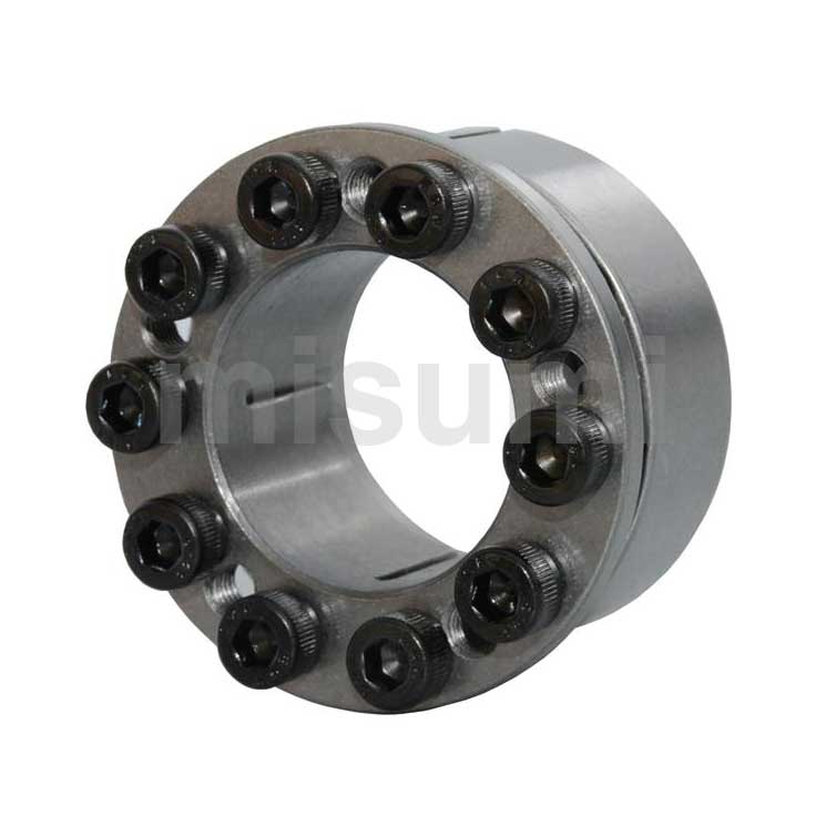
Keyless Bushings(Mechanical Lock), Straight With Centering Function
Part Number
Configured Part Number is shown.
It is a friction connector that can easily and firmly fix the shaft and the coupling (pulley, sprocket, gear, etc.) just by tightening the bolt.
The bolt tightening force is converted via the conical surface into the surface pressure on the inner diameter side and the outer diameter side, thus fixing the coupling and the shaft.
| Type | Body | |
 Material Material |  Surface Treatment Surface Treatment | |
| E-MLM | S45C | - |
Part Number
CAD Data download and 3D preview are not available because the part number has not yet been determined.
- *In order to open the CAD Data download and 3D preview screen, the part number must be fixed.
- Please confirm the part number from "Specification / Dimension"on the left side, and then perform the CAD Data Download / 3D Preview operation.
| Part Number |
|---|
| E-MLM40 |
| E-MLM42 |
| E-MLM45 |
| E-MLM50 |
| Part Number | Standard Unit Price | Minimum order quantity | Volume Discount | Days to Ship | Shaft Bore Dia. d (Ø) | Hub Dia. D (Ø) | Max. Allowable Torque Range (N•m) | Max. Allowable Torque (N•m) | Allowable Thrust Load (kN) | Overall Length (mm) | Outer Dia. D1 (or D) (Ø) |
|---|---|---|---|---|---|---|---|---|---|---|---|
SGD 20.60 | 1 Piece(s) | Available | 5 Day(s) | 40 | 62 | 1000.1~3000.0 | 1019 | 51.9 | 31 | 67 | |
SGD 22.70 | 1 Piece(s) | Available | 5 Day(s) | 42 | 64 | 1000.1~3000.0 | 1061 | 51.9 | 31 | 69 | |
SGD 23.70 | 1 Piece(s) | Available | 5 Day(s) | 45 | 67 | 1000.1~3000.0 | 1138 | 51.9 | 31.5 | 72 | |
SGD 28.80 | 1 Piece(s) | Available | Same day | 50 | 72 | 1000.1~3000.0 | 1768 | 72.7 | 32.5 | 77 |
Loading...
| Part Number | D | D1 | W | L1 | L2 | L3 | Clamp Screw | Mass (g) | Bore Tolerance (Initial State) μ m | |||
| Type | d | M×L | Quantity | Tightening Torque (N·m) | ||||||||
| E-MLM | 5 | 16 | 18.5 | 16 | 11.2 | 8 | 13 | M3X10 | 4 | 2.1 | 20 | +4.5 +0 |
| 8 | 21 | 23.5 | 18.5 | 12.5 | 9.5 | 14.5 | M4X12 | 5.1 | 40 | |||
| 10 | 23 | 25.5 | 19 | 13 | 15 | |||||||
| 12 | 26 | 28.5 | 22 | 15.5 | 10.5 | 18 | M4X14 | 6 | 60 | +5.5 +0 | ||
| 14 | 28 | 30.5 | 6 | |||||||||
| 15 | 29 | 31.5 | 23 | 16.5 | 11.5 | 19 | 70 | |||||
| 16 | 30 | 33 | 23.6 | 17.5 | 12 | 20 | ||||||
| 19 | 33 | 35.5 | 24 | 12.5 | 8 | 80 | +6.5 +0 | |||||
| 20 | 38 | 42 | 29 | 21 | 15.5 | 24 | M5X18 | 10 | 130 | |||
| 22 | 40 | 44 | 140 | |||||||||
| 25 | 43 | 47 | 31 | 23 | 17.5 | 26 | 170 | |||||
| 30 | 48 | 52 | 31.5 | 26.5 | 10 | 190 | ||||||
| 32 | 50 | 54 | 32.5 | 24 | 18.5 | 27.5 | 210 | +7 +0 | ||||
| 35 | 57 | 62 | 36 | 26 | 19.5 | 30 | M6X20 | 8 | 17 | 320 | ||
| 40 | 62 | 67 | 37 | 27 | 20.5 | 31 | 10 | 380 | ||||
| 42 | 64 | 69 | ||||||||||
| 45 | 67 | 72 | 37.5 | 27.5 | 21 | 31.5 | 400 | |||||
| 50 | 72 | 77 | 38.5 | 27.5 | 21.5 | 32.5 | 14 | 460 | ||||
| Type | Body | |
| Material | Surface Treatment | |
| E-MLM | S45C | - |
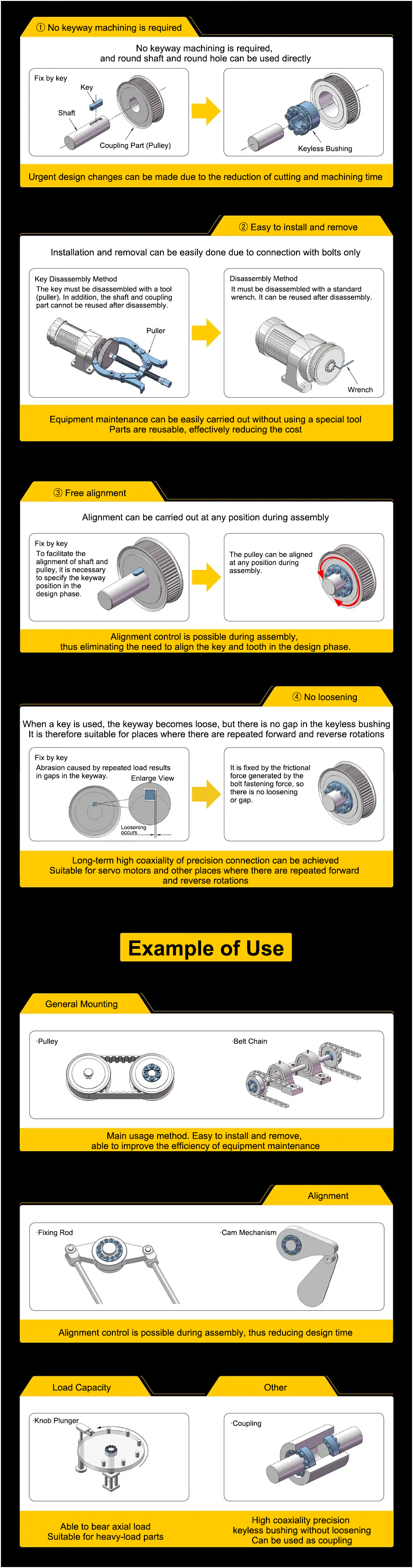
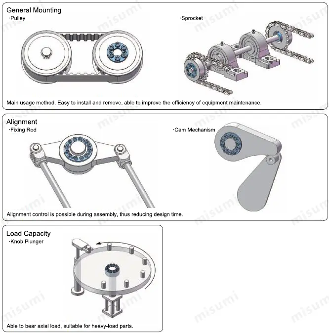
Example of Use

①Applying lubricant Please wipe off the stains on the shaft surface and apply a layer of lubricant or grease. *Do not use any lubricant or grease that contains molybdenum abrasion inhibiting agent.
②Positioning Temporarily assemble the economy series keyless bushing and the coupling, and insert the assembly into the shaft for positioning.
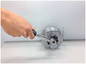
③Screwing bolts Use a torque wrench to tighten the fastening bolts diagonally in sequence.
Firstly tighten the bolts lightly (with 1/2 of the tightening torque), then tighten them with the specified tightening torque.
④Tightening bolts Finally tighten the bolts circumferentially in sequence with the specified tightening torque.

①Removing bolts Loosen the fastening bolts circumferentially in sequence.
②Removing economy series keyless bushing Insert the bolt into the threaded hole for removal, and screw in evenly.

①The inner bushing (body) and outer bushing (collar, side ring) of the economy series keyless bushing may vibrate slightly during transportation, and their conical surfaces may wedge against each other.
When installing, loosen the bolts and nuts first, disassemble the body, remove the wedge on the conical surface, and then proceed with assembly.
②If the bolts are tightened before installation into the wheel hole or insertion into the shaft, it will cause deformation of the economy series keyless bushing and make it unusable.
③Be sure to use accessory bolts for clamp screws.
Related Products
| Keyless High Torque Timing Pulleys | Keyless Sprockets |
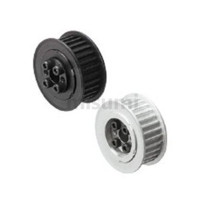 | 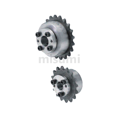 |
| Features Shaft machining of keyways, etc. is not required. As shaft machining is not required, the shaft strength will not be reduced. Easy to perform positioning. | Features The positions of teeth and keys in the keyway are fixed, but the positions of teeth can be freely adjusted by using keyless sprockets, thus facilitating the alignment. |
Use a torque wrench when assembling the economy series keyless bushing.
Please use properly after considering the assembling space.
Step ② Confirm the materials and surface treatment
Materials and surface treatment can be selected for MISUMI economy series keyless bushing. It is recommended to use electroless nickel plating or stainless steel in places where there is humidity, condensation or a large amount of water. Please note that the provided material and surface treatment vary with product series.
Step ③ Confirm the allowable input load of the economy series keyless bushing
Calculate the torque and load applied on the economy series keyless bushing, and confirm whether they are lower than the allowable values set for each product series.
·Input torque value of keyless bushing < Max. allowable torque of keyless bushing
·Axial load applied on the economy series keyless bushing < Allowable axial load of economy series keyless bushing
Note When the shaft or wheel hole has keyways, it can be used if the groove width falls in the range of JIS specifications, but the allowable torque and allowable axial load will decrease by 15~20%.
Step ④ Confirm the rigidity of the shaft and wheel hole
·For the shaft, confirm the yield stress of the shaft material used, and choose a material with a yield stress higher than the wheel hole side pressure set for each product series×1.2.
·For the wheel hole, confirm the yield stress of the wheel hole material used, and choose a material with a yield stress higher than the wheel hole side pressure set for each product series×1.2.
The minimum outer diameter of the couping has been calculated for typical materials. Please refer to Minimum Wheel Hole Outer Diameter Table for each product series.
Basic Information
| Series | Standard Type | Body Material | S45C | Centering Function | With Centering Function |
|---|---|---|---|---|---|
| Main Body Surface Treatment | None | Tightening Structure | Single Cone Type | Structure | Mechanical Type (Wedge Type) |
| Locking Screw Qty. | Multiple pcs. |
Specification/Dimensions
-
Shaft Bore Dia. d(Ø)
-
Hub Dia. D(Ø)
-
Max. Allowable Torque(N•m)
-
Overall Length(mm)
-
Outer Dia. D1 (or D)(Ø)
-
Max. Allowable Torque Range(N•m)
-
CAD
- 2D
- 3D
Days to Ship
-
- All
- Same day
- 5 Day(s) or Less
Specify Alterations
- The specifications and dimensions of some parts may not be fully covered. For exact details, refer to manufacturer catalogs .
Frequently asked question (FAQ)
- Question: What transmission components can be combined with economy series keyless bushings?
- Answer: Guide shafts and parts (pulleys, gears, sprockets), etc. can be easily installed for combined use.
- Question: Will they become loose after installation and prolonged use, and can they be used for reverse rotating mechanisms?
- Answer: There will be no loosening during use as long as the bolts are tightened, so it is particularly effective for repeated forward and reverse rotation.
- Question: Can the coaxiality be guaranteed if no keys are mounted and only bushings are used in the joint area?
- Answer: The coaxiality of the parts can be achieved simply by tightening the bolts to install them. There is no need for time-consuming key machining of the shaft and coupling part and the running-in process during assembly, thus reducing the total cost.
- Question: What is the tightening principle of the bushing?
- Answer: It converts the tightening force for bolt connection into the surface pressure on the inner diameter side through the conical surface, and there is no need for the time-consuming key machining of the shaft and coupling part and the running-in process during assembly, thus connecting the shaft and coupling part firmly.
- Question: How many materials are available for selection?
- Answer: Currently, MISUMI offers three material choices: steel, stainless steel, and aluminum alloy.
Tech Support
Payment Method
- Credit Card
- PayPal
- Bank Transfer
Social Media
MISUMI Contact
Copyright © MISUMI Corporation All Rights Reserved.
How can we improve?
How can we improve?