(!)Due to Microsoft's end of support for Internet Explorer 11 on 15/06/2022, this site does not support the recommended environment.
Instead, please kindly use other browsers like Google Chrome, Microsoft Edge or Mozilla Firefox.
50,000 Stock items for Same Day Ship Out.
All Categories
Categories
- Automation Components
A wide variety of standard and configurable components for factory automation engineers in industries such as automotive, semiconductor, packaging, medical and many more.
- Linear Motion
- Rotary Motion
- Connecting Parts
- Rotary Power Transmission
- Motors
- Conveyors & Material Handling
- Locating, Positioning, Jigs & Fixtures
- Inspection
- Sensors, Switches
- Pneumatics, Hydraulics
- Vacuum Components
- Hydraulic Equipment
- Discharging / Painting Devices
- Pipe, Tubes, Hoses & Fittings
- Modules, Units
- Heaters, Temperature Control
- Framing & Support
- Casters, Leveling Mounts, Posts
- Doors, Cabinet Hardware
- Springs, Shock Absorbers
- Adjusting, Fastening, Magnets
- Antivibration, Soundproofing Materials, Safety Products
- Fasteners
A good selection of accessories such as screws, bolts, washers and nuts that you may need for your daily engineering usage.
- Materials
Browse industrial materials ranging from heat insulating plates, sponges, to metal and plastic materials in different sizes to meet your various applications.
- Wiring Components
A wide variety of wiring parts for connecting and protecting control and PC parts including Connectors, Cables, Electric Wires, Crimping Terminals and more.
- LAN Cables / Industrial Network Cables
- Cables by Application
- Cables with Connectors
- RS232 / Personal Computers / AV Cables
- Wires/Cables
- Connectors (General Purpose)
- Crimp Terminals
- Zip Ties
- Cable Glands
- Cable Bushings/Clips/Stickers
- Screws/Spacers
- Cable Accessories
- Tubes
- Protection Tubes
- Ducts/Wiremolds
- General Purpose Tools
- Dedicated Tools
- Soldering Supplies
- Electrical & Controls
A wide variety of controls and PC parts for electrical engineers including Controls, Powers, PC parts and more.
- Cutting Tools
A wide variety of cutting tools for many uses and work materials including End Mills, Drills, Cutters, Reamers, Turning Tools and more.
- Carbide End Mills
- HSS End Mills
- Milling Cutter Inserts/Holders
- Customized Straight Blade End Mills
- Dedicated Cutters
- Turning Tools
- Drill Bits
- Screw-Hole-Related Tools
- Reamers
- Chamfering / Centering Tools
- Fixtures Related to Cutting Tools
- Step Drills
- Hole Saws
- Clean Key Cutters
- Core Drills (Tip Tools)
- Magnetic Drilling Machine Cutters
- Drill Bits for Electric Drilling Machines
- Woodworking Drill Cutters
- Drills for Concrete
- Processing Tools
A wide variety of tools and supplies used in processing including Machine Tools, Measurement Tools, Grinding and Polishing Supplies and more.
- Material Handling & Storage
A wide variety of goods used in shipment, material handling and warehouse including Tape supplies, Stretch film, Truck, Shelf, Crane and more.
- Tape Supplies
- Cushioning Materials
- Stretch Films
- Cardboard
- Plastic Bags
- PP Bands
- Magic Tapes / Tying Belts
- Rubber Bands
- Strings/Ropes
- Cable Ties
- Tags
- Labelers
- Unpacking Cutters
- Packing Support Equipment
- Cloth Sheets for Packing
- Conveyance/Dolly Carts
- Tool Wagons
- Tool Cabinets / Container Racks
- Lifters / Hand Pallets
- Container Pallets
- Storage Supplies
- Shelves/Racks
- Work Benches
- Suspended Clamps/Suspended Belts
- Jack Winches
- Chain Block Cranes
- Bottles/Containers
- Bicycle Storage Area
- Safety & General Supplies
A large variety of goods for every kind of factories and offices including Protection items, Cleaning supplies, sanitations, office supplies and more.
- Lab & Clean Room Supplies
A large variety of items used in R&D and Clean Room including research Equipment, Laboratory Essentials, Analysis Supplies, Clean Environment-Related Equipment and more.
- Press Die Components
Choose from thousands of standard stamping die components including Punch & Die, Gas Springs, Guide Components, Coil Springs and many more.
- Plastic Mold Components
Browse our wide variety of mold components including Ejector Pins, Sleeves, Leader Components, Sprue Bushings and many more.
- Ejector Pins
- Sleeves, Center Pins
- Core Pins
- Sprue bushings, Gates, and other components
- Date Mark Inserts, Recycle Mark Inserts, Pins with Gas Vent
- Undercut, Plates
- Leader Components, Components for Ejector Space
- Mold Opening Controllers
- Cooling or Heating Components
- Accessories, Others
- Components of Large Mold, Die Casting
- Injection Molding Components
Browse our injection molding components including Heating Items, Couplers, Hoses and more.
- Injection Molding Machine Products
- Accessories of Equipment
- Auxiliary Equipment
- Air Nippers
- Air Cylinders
- Air Chuck for Runner
- Chuck Board Components
- Frames
- Suction Components
- Parallel Air Chuck
- Special Air Chuck
- Chemical for Injection Molding
- Mold Maintenance
- Heating Items
- Heat Insulation Sheets
- Couplers, Plugs, One-touch Joints
- Tubes, Hoses, Peripheral Components
Search by Application
Brands


- Please be informed that our office is closed during the upcoming Labour Day Holiday in 2024. We would also like to inform you that there may be a potential delay in response/shipment from the supplier due to the Japan Golden Week holiday which falls from 29th April to 6th May 2024. Click here for details.
- Please Note our New Address (effective April 1, 2024): 331 North Bridge Rd, #05-01 Odeon 331, Singapore 188720.
Disc Couplings High Regidity Double Disc, Clamping Type


- Volume Discount
· C-SCPW series Disc Couplings High Rigidity Double Disc, Clamping Type
· Type of Coupling: C-SCPW.
· Applicable motor types: recommended for servo motors, stepping motors.
· Maximum Rotational Speed Range: 4001 ~ 10000 (r/min).
· Maximum Rotational Speed: 10000 (r/min).
· Allowable Angular Misalignment: 1.0, 1.2 and 1.5°
· Disc Type: Double Discs.
· Body material: Aluminum Alloy.
· Disc material: Stainless Steel.
· Lock bolt: Steel SCM435 surface treatment Ferro ferric Oxide Protective Film.
· Operating for working in high temperature -80 to 300 °C
· Accessories: Hex socket bolt (Clamping bolt).
Part Number
Configured Part Number is shown.
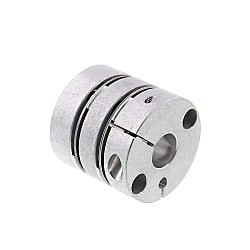
Coupling Product Overview
The disc coupling relies on the elastic deformation of the disc to compensate for the relative displacement of the connected two shafts, which is a high-performance flexible coupling with strong metal components.
It is characterized by compact structure, no backlash, high strength, long service life, no rotation clearance, no influence of temperature and oil pollution, acid resistance, alkali resistance and corrosion resistance.
Applicable motor types: recommended for servo motors, stepping motors and general motors.
Coupling Product Feature
1. Strong ability to compensate for misalignment between two axes. Compared with tooth coupling, angular displacement can be doubled. In case of radial displacement, reaction force is small, flexibility is large, and certain axial, radial and angular displacements are allowed.
2. It has obvious shock absorption, no noise and no wear.
3. Suitable for working in high temperature (-80+300) and harsh environment, and operate safely under shock and vibration conditions.
4. High transmission efficiency, up to 99.86%. Especially suitable for medium, high speed and high power transmission.
5. Simple structure, light weight, small in size and convenient assembly and disassembly. It can be assembled and disassembled without moving the machine (models with intermediate shaft), and requiring no lubrication.
6. It can accurately transmit the rotational speed without slip, and can be used for transmission of precision machinery
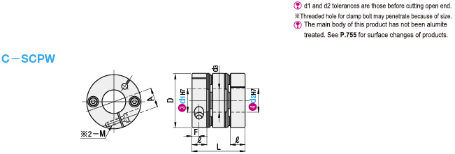
Dimensional Coupling Drawing
| Type | Parts |  Material Material |  Surface Treatment Surface Treatment |  Accessories Accessories |
| C-SCPW | Body | Aluminum | - | Hex socket bolt (Clamping bolt) |
| Disc | Stainless Steel | - | ||
| Lock Bolt | SCM435 | Ferroferric Oxide Protective Film |
Coupling Specifications Overview
Please order after selecting part number and parameters according to the selection steps
 to
to  .
.Part Number (Type· No.) No.) | - |  d1 d1 | - | d2 |
| C-SCPW34 | - | 10 | - | 14 |
| Part Number | d1, d2 selection (But d1≤d2) | D | d3 | L | ℓ | F | A | Fastening Bolt | ||||||||||||||||||
| Type | No. | M | Tightening torque (N·m) | |||||||||||||||||||||||
| C-SCPW | 16 | 4 | 5 | 6 | 16.6 | 6.5 | 23 | 7.2 | 3 | 5.3 | M2.6 | 1.0 | ||||||||||||||
| 21 | 4 | 5 | 6 | 8 | 21 | 9.5 | 24.5 | 7 | 3.5 | 7 | M2.6 | 1.2 | ||||||||||||||
| 28 | 6 | 6.35 | 8 | 10 | 28 | 12 | 32.2 | 9 | 4 | 9.5 | M3 | 1.7 | ||||||||||||||
| 34 | 6 | 6.35 | 8 | 10 | 11 | 12 | 14 | 34 | 15 | 35 | 9.8 | 5 | 12 | M3 | 1.7 | |||||||||||
| 46 | 8 | 10 | 11 | 12 | 14 | 15 | 16 | 17 | 19 | 46 | 22 | 44 | 12.6 | 6 | 16.5 | M4 | 4.1 | |||||||||
| 55 | 12 | 14 | 15 | 16 | 17 | 19 | 20 | 22 | 24 | 25 | 54.5 | 26 | 55 | 16 | 7 | 20.5 | M5 | 8.2 | ||||||||
■Characteristic Value
| Part Number | Allowable torque (N·m) | Allowable Angular Misalignment (°) | Allowable lateral misalignment (mm) | Static torsional stiffness (N·m/rad) | Maximum Rotational Speed (r/min) | Moment of inertia (kg·m2) | Allowable axial amplitude (mm) | Compensation coefficient | Weight (g) | |
| Type | No. | |||||||||
| C-SCPW | 16 | 0.5 | 1.0 | 0.10 | 500 | 10000 | 4.22×10⁻⁷ | ±0.20 | 1.5 | 11 |
| 21 | 1.0 | 800 | 1.11×10⁻⁶ | 17 | ||||||
| 28 | 1.5 | 1.2 | 0.15 | 3000 | 4.68×10⁻⁶ | 42 | ||||
| 34 | 4.0 | 1.5 | 0.20 | 4800 | 1.10×10⁻⁵ | 65 | ||||
| 46 | 10.0 | 0.25 | 11500 | 4.70×10⁻⁵ | ±0.30 | 151 | ||||
| 55 | 25.0 | 19000 | 1.19×10⁻⁴ | 260 | ||||||
 Static torsional stiffness, moment of inertia and weight are the values at the maximum shaft dia.Lateral misalignment, angular misalignment and axial amplitude are all single allowable values. If there are multiple deviations at the same time, the allowable value of each deviation will be reduced to 1/2 of the original value.
■Shaft slip torque(N·m)
When the shaft slip torque is less than the allowable torque, please use it below the shaft slip torque.| Part Number | d1, d2 | |||||||||||||||||
| Type | No. | 4 | 5 | 6 | 6.35 | 8 | 10 | 11 | 12 | 14 | 15 | 16 | 17 | 19 | 20 | 22 | 24 | 25 |
| C-SCPW | 16 | 0.5 | 0.5 | 0.5 | - | - | - | - | - | - | - | - | - | - | - | - | - | - |
| 21 | 1.0 | 1.0 | 1.0 | - | 1.0 | - | - | - | - | - | - | - | - | - | - | - | - | |
| 28 | - | - | 1.5 | 1.5 | 1.5 | 1.5 | - | - | - | - | - | - | - | - | - | - | - | |
| 34 | - | - | 2.5 | 2.5 | 4.0 | 4.0 | 4.0 | 4.0 | 4.0 | - | - | - | - | - | - | - | - | |
| 46 | - | - | - | - | 6.0 | 6.0 | 8.0 | 8.0 | 8.0 | 8.0 | 10 | 10 | 10 | - | - | - | - | |
| 55 | - | - | - | - | - | - | - | 16 | 16 | 19 | 25 | 25 | 25 | 25 | 25 | 25 | 25 | |
Coupling Precautions
1. The coupling allows axis deviation, and transmits rotation angle and torque, but when the axis deviation exceeds the allowable value, vibration will occur or the service life will be drastically reduced.
Be sure to make calibration and adjustment.
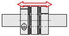
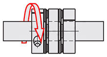
2. Axis deviation includes lateral misalignment (parallel error of two axes), angular misalignment (angular error of two axes) and axial amplitude (axial movement of shaft).
Please calibrate and adjust the shaft to ensure that the axis deviation is below the allowable value recorded in the dimension and performance table of each product.
3. The allowable value of axis deviation recorded in the dimension and performance table refers to the situation when either lateral misalignment, angular misalignment or axial amplitude occurs alone. When more than two axis deviations occur at the same time, the corresponding allowable values are halved respectively.
4. Axis deviation not only occurs when assembling to the device, but also is caused by vibration, thermal expansion and bearing wear in operation. Therefore, it is recommended to set the axis deviation below 1/3 of the allowable value.
Example of Use coupling
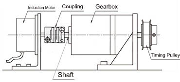
Use example of coupling 1: motor×gear box
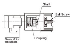
Use example of coupling 2: motor×ball screw
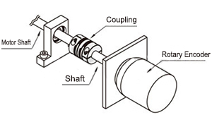
Use example of coupling 3: motor×encoder
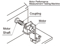
Use example of coupling 4: motor×measuring tester
Coupling Usage Method
STEP1 Insert the coupling
Confirm that the clamping bolt has been unscrewed, and then remove the dust, foreign matter and oil from the shaft and coupling bore.
Then, when inserting the coupling into the shaft, please be careful not to put the disc under excessive stress such as compression or tension.
STEP2 Use fixture to adjust
Please use fixture to adjust and fix the concentricity of the left and right hubs of the coupling with high accuracy.
STEP3 Simple lateral misalignment and angular misalignment confirmation
Under the condition of unscrewed bolts, make the coupling slide axially and confirm its smooth movement.
Then, rotate the coupling to make sure it moves smoothly.
Lateral misalignment is not allowed for single disc type coupling, so carry out positioning securely.STEP4 Installation
Please adjust the shaft insertion amount according to the dimension ℓ in the product catalog, and use a torque wrench to tighten with the specified torque.
* If the specified torque cannot be reached once, please cross fasten the left and right clamps twice or three times.
Part Number
CAD Data download and 3D preview are not available because the part number has not yet been determined.
- *In order to open the CAD Data download and 3D preview screen, the part number must be fixed.
- Please confirm the part number from "Specification / Dimension"on the left side, and then perform the CAD Data Download / 3D Preview operation.
| Part Number | Standard Unit Price | Minimum order quantity | Volume Discount | Days to Ship | Shaft Bore Dia. 1 d1 (or d) (Ø) | Shaft Bore Dia. 2 d2 (or d) (Ø) | O.D. (Ø) | Overall Length (mm) | Allowable Torque Range (N•m) | Allowable Torque (N•m) | Allowable Angular Misalignment (deg) | Allowable Lateral Misalignment (mm) | Allowable Lateral Misalignment Range (mm) | Allowable Axial Misalignment (mm) | Moment of Inertia (kg・m2) |
|---|---|---|---|---|---|---|---|---|---|---|---|---|---|---|---|
SGD 67.78 | 1 Piece(s) | Available | Same day | 6 | 6 | 34 | 35 | 3.01~5.00 | 4 | 1.5 | 0.2 | 0.02~0.2 | 0.2 | 1.1×10⁻⁵ | |
SGD 67.78 | 1 Piece(s) | Available | 7 Day(s) | 6 | 6.35 | 34 | 35 | 3.01~5.00 | 4 | 1.5 | 0.2 | 0.02~0.2 | 0.2 | 1.1×10⁻⁵ | |
SGD 67.78 | 1 Piece(s) | Available | 6 Day(s) | 6 | 8 | 34 | 35 | 3.01~5.00 | 4 | 1.5 | 0.2 | 0.02~0.2 | 0.2 | 1.1×10⁻⁵ | |
SGD 67.78 | 1 Piece(s) | Available | 7 Day(s) | 6 | 10 | 34 | 35 | 3.01~5.00 | 4 | 1.5 | 0.2 | 0.02~0.2 | 0.2 | 1.1×10⁻⁵ | |
SGD 67.78 | 1 Piece(s) | Available | Same day | 6 | 11 | 34 | 35 | 3.01~5.00 | 4 | 1.5 | 0.2 | 0.02~0.2 | 0.2 | 1.1×10⁻⁵ | |
SGD 67.78 | 1 Piece(s) | Available | Same day | 6 | 12 | 34 | 35 | 3.01~5.00 | 4 | 1.5 | 0.2 | 0.02~0.2 | 0.2 | 1.1×10⁻⁵ | |
SGD 67.78 | 1 Piece(s) | Available | Same day | 6 | 14 | 34 | 35 | 3.01~5.00 | 4 | 1.5 | 0.2 | 0.02~0.2 | 0.2 | 1.1×10⁻⁵ | |
SGD 67.78 | 1 Piece(s) | Available | 7 Day(s) | 6.35 | 6.35 | 34 | 35 | 3.01~5.00 | 4 | 1.5 | 0.2 | 0.02~0.2 | 0.2 | 1.1×10⁻⁵ | |
SGD 67.78 | 1 Piece(s) | Available | Same day | 6.35 | 8 | 34 | 35 | 3.01~5.00 | 4 | 1.5 | 0.2 | 0.02~0.2 | 0.2 | 1.1×10⁻⁵ | |
SGD 67.78 | 1 Piece(s) | Available | 6 Day(s) | 6.35 | 10 | 34 | 35 | 3.01~5.00 | 4 | 1.5 | 0.2 | 0.02~0.2 | 0.2 | 1.1×10⁻⁵ | |
SGD 67.78 | 1 Piece(s) | Available | 7 Day(s) | 6.35 | 11 | 34 | 35 | 3.01~5.00 | 4 | 1.5 | 0.2 | 0.02~0.2 | 0.2 | 1.1×10⁻⁵ | |
SGD 67.78 | 1 Piece(s) | Available | 6 Day(s) | 6.35 | 12 | 34 | 35 | 3.01~5.00 | 4 | 1.5 | 0.2 | 0.02~0.2 | 0.2 | 1.1×10⁻⁵ | |
SGD 67.78 | 1 Piece(s) | Available | 7 Day(s) | 6.35 | 14 | 34 | 35 | 3.01~5.00 | 4 | 1.5 | 0.2 | 0.02~0.2 | 0.2 | 1.1×10⁻⁵ | |
SGD 67.78 | 1 Piece(s) | Available | 6 Day(s) | 8 | 8 | 34 | 35 | 3.01~5.00 | 4 | 1.5 | 0.2 | 0.02~0.2 | 0.2 | 1.1×10⁻⁵ | |
SGD 67.78 | 1 Piece(s) | Available | 6 Day(s) | 8 | 10 | 34 | 35 | 3.01~5.00 | 4 | 1.5 | 0.2 | 0.02~0.2 | 0.2 | 1.1×10⁻⁵ | |
SGD 67.78 | 1 Piece(s) | Available | Same day | 8 | 11 | 34 | 35 | 3.01~5.00 | 4 | 1.5 | 0.2 | 0.02~0.2 | 0.2 | 1.1×10⁻⁵ | |
SGD 67.78 | 1 Piece(s) | Available | Same day | 8 | 12 | 34 | 35 | 3.01~5.00 | 4 | 1.5 | 0.2 | 0.02~0.2 | 0.2 | 1.1×10⁻⁵ | |
SGD 67.78 | 1 Piece(s) | Available | Same day | 8 | 14 | 34 | 35 | 3.01~5.00 | 4 | 1.5 | 0.2 | 0.02~0.2 | 0.2 | 1.1×10⁻⁵ | |
SGD 67.78 | 1 Piece(s) | Available | Same day | 10 | 10 | 34 | 35 | 3.01~5.00 | 4 | 1.5 | 0.2 | 0.02~0.2 | 0.2 | 1.1×10⁻⁵ | |
SGD 67.78 | 1 Piece(s) | Available | 6 Day(s) | 10 | 11 | 34 | 35 | 3.01~5.00 | 4 | 1.5 | 0.2 | 0.02~0.2 | 0.2 | 1.1×10⁻⁵ | |
SGD 67.78 | 1 Piece(s) | Available | Same day | 10 | 12 | 34 | 35 | 3.01~5.00 | 4 | 1.5 | 0.2 | 0.02~0.2 | 0.2 | 1.1×10⁻⁵ | |
SGD 67.73 | 1 Piece(s) | Available | Same day | 10 | 14 | 34 | 35 | 3.01~5.00 | 4 | 1.5 | 0.2 | 0.02~0.2 | 0.2 | 1.1×10⁻⁵ | |
SGD 67.78 | 1 Piece(s) | Available | 6 Day(s) | 11 | 11 | 34 | 35 | 3.01~5.00 | 4 | 1.5 | 0.2 | 0.02~0.2 | 0.2 | 1.1×10⁻⁵ | |
SGD 67.78 | 1 Piece(s) | Available | 6 Day(s) | 11 | 12 | 34 | 35 | 3.01~5.00 | 4 | 1.5 | 0.2 | 0.02~0.2 | 0.2 | 1.1×10⁻⁵ | |
SGD 67.78 | 1 Piece(s) | Available | 6 Day(s) | 11 | 14 | 34 | 35 | 3.01~5.00 | 4 | 1.5 | 0.2 | 0.02~0.2 | 0.2 | 1.1×10⁻⁵ | |
SGD 67.78 | 1 Piece(s) | Available | 6 Day(s) | 12 | 12 | 34 | 35 | 3.01~5.00 | 4 | 1.5 | 0.2 | 0.02~0.2 | 0.2 | 1.1×10⁻⁵ | |
SGD 67.78 | 1 Piece(s) | Available | Same day | 12 | 14 | 34 | 35 | 3.01~5.00 | 4 | 1.5 | 0.2 | 0.02~0.2 | 0.2 | 1.1×10⁻⁵ | |
SGD 67.78 | 1 Piece(s) | Available | 6 Day(s) | 14 | 14 | 34 | 35 | 3.01~5.00 | 4 | 1.5 | 0.2 | 0.02~0.2 | 0.2 | 1.1×10⁻⁵ |
Loading...
Basic Information
| Series Name | Disc | Application | For Servo Motors / Stepping Motor | Features | High Torsional Rigidity / High Torque Type / Zero Backlash |
|---|---|---|---|---|---|
| Allowable Misalignment | Angular Misalignment / Eccentricity / Axial Misalignment | Max. Rotational Speed Range(r/min) | 4001~10000 | Body Material | Aluminum Alloy |
| Product Category | Coupling Main Body | Max. Rotational Speed(r/min) | 10000 | Disc Material | Stainless Steel |
| Single/Double | Double | Shaft Bore Shape | Standard Bore | Shaft Tightening Method | Fastening Bolt |
Specification/Dimensions
-
Shaft Bore Dia. 1 d1 (or d)(Ø)
-
Shaft Bore Dia. 2 d2 (or d)(Ø)
-
O.D.(Ø)
-
Overall Length(mm)
-
Allowable Torque(N•m)
-
Allowable Angular Misalignment(deg)
-
Allowable Lateral Misalignment(mm)
-
Allowable Lateral Misalignment Range(mm)
-
type
- C-SCPW
-
Allowable Torque Range(N•m)
-
CAD
- 2D
- 3D
Days to Ship
-
- All
- Same day
- 6 Day(s) or Less
- 7 Day(s) or Less
Specify Alterations
- The specifications and dimensions of some parts may not be fully covered. For exact details, refer to manufacturer catalogs .
Frequently asked question (FAQ)
- Question: Which disc type coupling is better, single disc type or double disc type?
-
Answer:
Double disc type can absorb angular misalignment and lateral misalignment, but the total length will increase.
Although the total length of the single disc type is short, it is only suitable for applications with narrow space because lateral misalignment is not allowed in the structure.
Special attention should be paid to centering during use. - Question: Abnormal sound or vibration occurs during use of disc type coupling.
-
Answer:
When a servo motor is used, the frequency of the mechanical resonance suppression filter is set as its inherent vibration frequency in the control system to suppress sound and vibration.
When using a stepping motor, the rotational speed can be finely adjusted, or the vibration can be absorbed and suppressed by the high damping rubber type coupling with obvious attenuation effect. - Question: How to select according to the purpose, environment, working conditions?
- Answer: Please refer to the MISUMI website.
Tech Support
- Factory Automation, Electronics, Tools, & MRO (Maintenance, Repair and Operations)
- Tel:(65) 6733 7211 / FAX:(65) 6733 0211
- 9:00am - 6:00pm (Monday - Friday)
- Technical Inquiry
Payment Method
- Credit Card
- PayPal
- Bank Transfer
Social Media
MISUMI Contact
Copyright © MISUMI Corporation All Rights Reserved.
How can we improve?
How can we improve?