(!)Due to
Microsoft's end of support for Internet Explorer 11 on 15/06/2022, this site does not support the recommended
environment.
Instead, please kindly use other browsers like Google Chrome, Microsoft Edge or Mozilla
Firefox.
- Website Upgrade Completed! System improvements are now LIVE to improve your Ordering experience. You may be logged out after the website update, please log in again.
- MISUMI WhatsApp service is temporarily unavailable. Kindly contact us via “Chat now”
Linear System Lifespan Calculation 1
Allowable load
・Basic load rating (C)
The basic dynamic load rating is a load of constant direction and magnitude that allows 90% of a group of identical linear systems to run individually under the same conditions for 50 × 10^3 m without material damage due to rolling fatigue.
・Basic static load rating (Co)
The basic static load rating is the static load at which the sum of the permanent deformation of the rolling element and the permanent deformation of the rolling surface is 0.0001 times the diameter of the rolling element at the contact area under maximum stress.
・Allowable statically moment (MP, MY, MR)
The limit value of the static moment load that is subjected when a moment load is applied is determined by the amount of permanent deformation similar to the basic static load rating Co.
・Static factor of safety (fS)
The basic static load rating Co, which is applied at rest or during low-speed motion, is divided by the static factor of safety fS shown in Table-1, depending on the usage conditions.
Table 1 Static factor of safety (lower limit of fS)
| Usage conditions | Lower limit of fS |
|---|---|
| Under normal operating conditions | 1~2 |
| When smooth travel performance is required | 2~4 |
| When subjected to vibrations and impacts | 3~5 |
Allowable load (N) ≦ Co/fS
Allowable moment (N・m) ≦ (MP, MY, MR)/fS
fS: static factor of safety
Co: basic static load rating (N)
MP, MY, MR: allowable static moment
Lifespan
When a linear system undergoes linear reciprocating motion under load, repeated stressing constantly acts on the rolling elements and rolling surfaces, causing scaly damage called flaking due to material fatigue. The total distance traveled before the first flaking occurs is called the lifespan of the linear system.
・Rated lifespan (L)
Rated lifespan is the total distance that 90% of a group of identical linear systems can reach without flaking when run individually under the same conditions.
The rated lifespan can be determined from the basic load rating and the load applied to the linear system as follows.
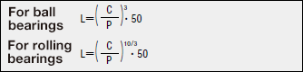
L: rated lifespan (km)
C: basic load rating (N)
P: acting load (N)
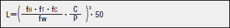
For using a linear system, load calculations must first be performed. It is not easy to calculate the load in linear reciprocating motion, because vibration and shock during the motion, as well as the distribution of the load to the linear system, should be fully considered. Operating temperature and other factors also have a significant impact on lifespan. Taking into account these conditions, the above formula is as follows.
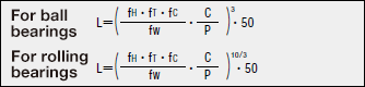
L: rated lifespan (km)
fH: hardness factor (See Fig. 1)
C: basic load rating (N)
fT: temperature factor (See Fig. 2)
P: acting load (N)
fC: contact factor (See Fig. 3)
fW: load factor (See Fig. 4)
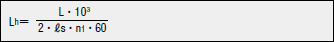
Lifespan can be calculated by determining the distance traveled per unit of time. If the stroke length and the number of strokes are constant, the following formula is used.
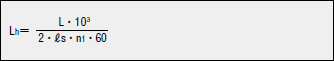
Lh: lifespan time (hr)
ℓs: Stroke length (m)
L: rated lifespan (km)
n1: Reciprocations per minute (cpm)
Friction resistance and required thrust
The frictional resistance (required thrust) is determined from the load and the inherent seal resistance of the system using the following equation.
F=μ・W+f
F: friction resistance (N)
μ: dynamic coefficient of friction
W: applied load
f: seal resistance (2N to 5N)
Table 2 Dynamic coefficient of friction
| Type | Dynamic coefficient of friction (μ) |
|---|---|
| Miniature linear guide | 0.004~0.006 |
| Medium duty linear guide | 0.002~0.003 |
| Slideway | 0.001~0.003 |
| Slide table | 0.001~0.003 |
| Linear bushing | 0.002~0.003 |
| Linear ball bushing | 0.0006~0.0012 |
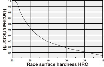
・Hardness factor (fH)
For using linear systems, the shafts that come into contact with the ball bearings must also be sufficiently hard. Failure to obtain adequate hardness will result in reduced allowable load and consequently shorter lifespan.
Correct the rated lifespan by the hardness factor.
Fig. 1 Hardness factor
・Contact factor (fC)
In actual use, two or more linear systems are generally used for a single shaft. In this case, the load applied to each linear system varies with machining accuracy and is not equally distributed. As a result, the allowable load per linear system varies depending on the number of linear systems per shaft.
Correct the rated lifespan using the contact factor in Table 3.
・Load factor (fW)
For calculating the loads acting on a linear system, it is important to accurately determine not only the weight of the object, but also the inertial forces or moment loads due to the speed of motion, and their respective changes over time. However, in addition to the constant repetition of starting and stopping in reciprocating motion, vibration and shock factors are also considered, making accurate calculations difficult.
Therefore, the load factors in Table-4 are used to simplify the lifespan calculation.
Linear bushing
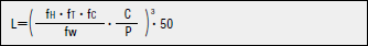
The rated lifespan can be determined from the basic load rating and the load applied to the linear bushing as follows.
L: rated lifespan (km)
fH: hardness factor (See Fig. 1)
C: basic load rating (N)
fT: temperature factor (See Fig. 2)
P: acting load (N)
fC: contact factor (See Fig. 3)
fW: load factor (See Fig. 4)
Lifespan can be calculated by determining the distance traveled per unit of time. If the stroke length and the number of strokes are constant, the following formula is used.
Lh: Lifespan time (hr)
ℓs: Stroke length (m)
L: rated lifespan (km)
n1: Reciprocations per minute (cpm)
・Temperature factor (fT)
When the temperature of the linear system exceeds 100°C, the hardness of the linear system and shaft decreases, resulting in a lower allowable load and shorter lifespan than when used at room temperature.
Correct the rated lifespan using the temperature factor.
Fig. 2 Temperature factor
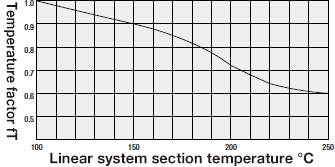
Table 3: Contact factor
| Number of bearings per shaft | Contact factor fc |
|---|---|
| 1 | 1.00 |
| 2 | 0.81 |
| 3 | 0.72 |
| 4 | 0.66 |
| 5 | 0.61 |
Table 4: Load factor
| Usage conditions | fw |
|---|---|
| No external impact vibration and the slow speed at 15 m/min or less |
1.0~1.5 |
| No significant impact vibration and the medium speed at 60 m/min or less |
1.5~2.0 |
| External impact vibration and the high speed exceeding 60 m/min |
2.0~3.5 |
Linear ball bushing
The rated lifespan can be determined from the basic load rating and the load applied to the linear ball bushing as follows.
L: rated lifespan (km)
fH: hardness factor (See Fig. 1)
C: basic load rating (N)
fT: temperature factor (See Fig. 2)
P: acting load (N)
fC: contact factor (See Fig. 3)
fW: load factor (See Fig. 4)
Lifespan time
For rotary and reciprocating motion
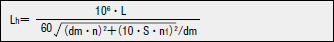
For reciprocating motion
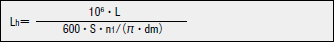
Lh: lifespan time (hr)
S: stroke length (mm)
n: rotational speed per minute (rpm)
n1: strokes per minute (cpm)
dm: pitch circle diameter of ball bearing pitch ≒1.15 dr
Allowable values for rotary and reciprocating motion
DN≧dm・n+10・S・n1
PDF list
Payment Method
- Credit Card
- PayPal
- Bank Transfer
Social Media
MISUMI Contact
Copyright © MISUMI Corporation All Rights Reserved.