(!)Due to
Microsoft's end of support for Internet Explorer 11 on 15/06/2022, this site does not support the recommended
environment.
Instead, please kindly use other browsers like Google Chrome, Microsoft Edge or Mozilla
Firefox.
- Website Upgrade Completed! System improvements are now LIVE to improve your Ordering experience. You may be logged out after the website update, please log in again.
- MISUMI WhatsApp service is temporarily unavailable. Kindly contact us via “Chat now”
Vacuum Pad Calculation Examples
- System configuration methods
- Workpiece weight calculations
- Vacuum pad theoretical holding power
- Selection of a vacuum pad
System configuration methods
Here, the procedure from theory to practice for configuring a vacuum system will be explained using an example.
This example uses the following workpiece and transfer system and is divided into 3 cases to be examined.
Workpiece
- Material:
- Steel plate (the state where they are stacked on pallets)
- Surface:
- Smooth, flat and dry
- Dimensions:
-
Maximum length 2,500mm
Maximum width 1,250mm
Maximum thickness 2.5mm
Weight approx. 60kg
Transfer system: Gantry (Gate type) transfer unit
- Compressed air:
- 0.8 MPa
- Control voltage:
- 24V DC
- Required work:
-
Horizontal Pick & Place
Lift 1 steel plate from the pallet, transfer it horizontally, and position it on the machining center.
- Maximum acceleration:
-
X, Y axis: 5 m/s2
Z axis: 5 m/s2
- Cycle time:
- 30 seconds
- Planned time:
-
Pickup: < 1 second
Release: < 1 second
Workpiece weight calculations
First, determine the workpiece weight (m). The workpiece weight is required for various calculations.
- m =
- L x B x H x ρ
- m =
- weight [kg]
- L =
- length [m]
- B =
- width [m]
- H =
- height [m]
- p =
- density [kg/m3]
In this example:
- m =
- 2.5m x 1.25m x 0.0025m x 7,850kg/m3
- m =
- 61.33kg
Vacuum pad theoretical holding power
The vacuum pad must be able to handle not only workpiece weight, but also the acceleration
force.
The safety factor should be at least 1.5 if the workpiece is smooth and does not have
breathability. The safety factor should be 2.0 or more for dangerous workpieces, breathable
workpieces, and workpieces with a rough or uneven surface. In addition, the safety factor of 2.0
or more shall be used when conditions such as acceleration and coefficient of friction are not
known or can’t be grasped accurately.
Case I:
When setting the vacuum pad horizontally and moving the workpiece in the vertical direction,
pick up the workpiece (in this example, a steel plate with dimensions of 2.5 × 1.25 m) from the pallet and lift it at an acceleration of 5 m/s2. There should be no horizontal movement.
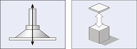
Position the vacuum pad on the workpiece from the horizontal direction and lift the workpiece.
- FTH =
- m x (g + a) x S
- FTH =
- theoretical holding power [N]
- m =
- weight [kg]
- g:
- gravitational acceleration [9.81 m/s2]
- a =
- handling system acceleration [m/s2]
- S =
- safety factor (It should be at least 1.5. It should be 2.0 or more for dangerous workpieces, breathable workpieces, and workpieces with a rough or uneven surface)
In this example:
- FTH =
- 61.33kg x (9.81m/s2 + 5m/s2) x 1.5
- FTH =
- 1,363N
Case II:
When setting the vacuum pad horizontally and moving the workpiece in the horizontal
direction
lift the workpiece (steel plate with dimensions of 2.5 × 1.25 m) vertically and transport it horizontally. Acceleration is 5 m/s2.
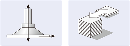
Position the vacuum pad on the workpiece from the horizontal direction, and move the workpiece to the side.
- FTH =
- m x (g + a / μ) x S
- FTH =
- theoretical holding power [N]
- Fa =
- acceleration force = m × a
- m =
- weight [kg]
- g:
- gravitational acceleration [9.81 m/s2]
- a =
-
transport system acceleration [m/s2]
(Be cautious about workpiece release in an emergency)
- μ:
-
coefficient of friction
= 0.1 (surface to which oil adheres)
= 0.2 to 0.3 (wet surface)
= 0.5 (wood, metal, glass, stone, etc.)
= 0.6 (rough surface)
- S =
- safety factor (It should be at least 1.5. It should be 2.0 or more for dangerous workpieces, breathable workpieces, and workpieces with a rough or uneven surface)
In this example:
- FTH =
- 61.33kg x (9.81m/s2 + 5m/s2 / 0.5) x 1.5
- FTH =
- 1,822N
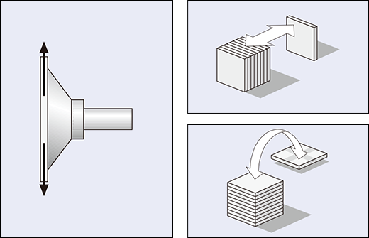
Case III:
When picking up the workpiece and moving the vacuum pad in the vertical direction,
pick up the workpiece (steel plate with dimensions of 2.5 × 1.25 m) from the pallet and move it at an acceleration of 5 m/s2 while rotating it.
- FTH =
- (m/μ) x (g+a) x S
- FTH =
- theoretical holding power [N]
- m =
- weight [kg]
- g:
- gravitational acceleration [9.81 m/s2]
- a =
-
transport system acceleration [m/s2]
(Be cautious about workpiece release in an emergency)
- μ:
-
coefficient of friction
= 0.1 (surface to which oil adheres)
= 0.2 to 0.3 (wet surface)
= 0.5 (wood, metal, glass, stone, etc.)
= 0.6 (rough surface)
- S =
- safety factor (It should be at least 1.5. It should be 2.0 or more for dangerous workpieces, breathable workpieces, and workpieces with a rough or uneven surface)
In this example:
- FTH =
- (61.33kg/0.5) x (9.81m/s2 + 5m/s2) x 2
- FTH =
- 3,633N
Comparison of cases I to III:
As shown in these examples, the required work is to lift the workpiece from a pallet, move it
laterally, and position it on a machining center. Accordingly, since there is no rotational
motion as in case III, only the case II needs to be considered.
In this case, the theoretical maximum holding power (FTH) is 1,822N. This force has
an effect on
the vacuum pad during horizontal transfer of the workpiece. Let’s proceed with a calculation
based on this value for a safe system configuration.
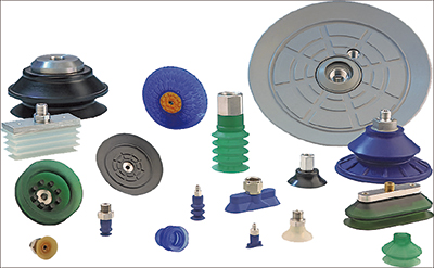
Selection of a vacuum pad
The theoretical holding power by calculation is the required force for the vacuum pad to safely transfer the workpiece.
Vacuum pad selected in this example:
Flat Vacuum Pad SAF (Nitrile rubber)
This vacuum pad is an excellent solution for cost-effectiveness when transporting smooth and flat workpieces.
In this case, it is necessary to decide whether the theoretical holding power based on calculations is carried by a piece of vacuum pad or divided by multiple vacuum pads.
For the steel plate (2,500 mm × 1,250 mm) as in these examples, normally 6 to 8 vacuum pads are used. The most important point that needs to be considered when determining the number of vacuum pads is that the steel plate does not bend during transport.
Calculation of holding force F S [N] required for 1 pc. of vacuum pad
- FS =
- FTH/n
- FS =
- holding force
- FTH =
- theoretical holding power
- n =
- number of vacuum pads
- In this example:
-
FS = 1,822N / 6
FS = 304N
The technical data for the Vacuum Pad SAF shows that, if 6 vacuum pads of this type are used, SAF100-M10-1.5 (100 mm in diameter, holding force of 430N) needs to be used.
- FS =
- 1,822N/8
- FS =
- 228N
The technical data for the Vacuum Pad SAF shows that, if 8 vacuum pads of this type are used, SAF80-M10-1.5 (80 mm in diameter, holding force of 272N) needs to be used.
Vacuum pad selected in this example:
Vacuum Pad SAF100-M10-1.5 (6 pcs.)
2.5mm thick steel plate can be lifted and transported with 6 vacuum pads.
Important:
The holding force of the vacuum pad must be larger than the calculated theoretical holding power.
PDF list
Payment Method
- Credit Card
- PayPal
- Bank Transfer
Social Media
MISUMI Contact
Copyright © MISUMI Corporation All Rights Reserved.