(!)Due to
Microsoft's end of support for Internet Explorer 11 on 15/06/2022, this site does not support the recommended
environment.
Instead, please kindly use other browsers like Google Chrome, Microsoft Edge or Mozilla
Firefox.
- Website Upgrade Completed! System improvements are now LIVE to improve your Ordering experience. You may be logged out after the website update, please log in again.
- MISUMI WhatsApp service is temporarily unavailable. Kindly contact us via “Chat now”
Toggle Mechanism (Fundamentals of Booster Mechanism)
This article is Part 5 in the Fundamentals Series. Could you move the earth using leverage? An introduction to booster mechanism with examples of how levers, toggles and crank mechanisms are used
- Boost mechanisms and lever mechanisms
- Toggle mechanism
- Usage example of booster mechanism
Booster Mechanism (2): Toggle Mechanism
A toggle mechanism is a type of link mechanism consisting of 2 links and a slider. The input causes the component to move in the input direction, and the output is increased by a booster mechanism.
Toggle mechanism
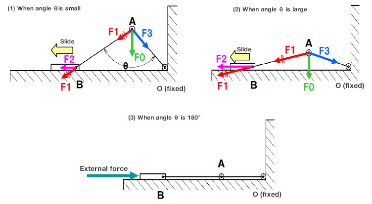
Fig. 2 Toggle mechanism
|
Fig. 2 illustrates the toggle mechanism in which joint O is fixed, and A is not fixed but free to move.
If the force acting vertically from joint A is F0, the horizontal force acting on B when F0 is applied is F2, and assuming that the lengths of joints OA and AB are the same,
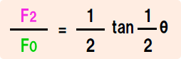 is valid.
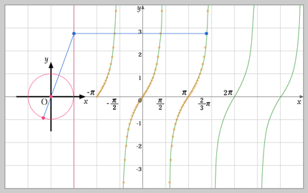
Because the tangent has the cycle shown in Figure 3 on the right, the force increases rapidly as the angle of θ/2 increases to 90°.
Thus, the closer OA and AB approach a straight line (180°), the more rapidly F2 increases.
Furthermore, when the angle θ/2 is 90°, the link becomes a straight line and the structure is very resistant to external forces even when the input is removed.
This toggle mechanism is applied to toggle clamps.
Fig. 3 Tangent graph
Application of toggle mechanism Toggle clamp
A toggle clamp is a jig that clamps objects using a toggle mechanism. Please refer to Fig. 4.
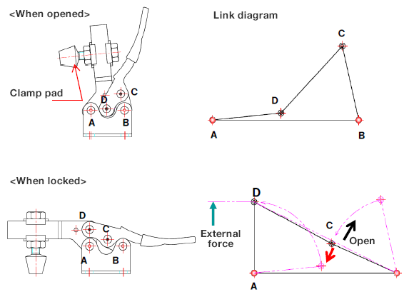
Fig. 4 consists of a 4-bar linkage with A and B fixed. BC and CD are the toggle mechanism, which means that link D operates on the input from link C. This movement causes the clamping pad to clamp the corresponding part.
When locked, link C enters slightly inside the line connecting BD and locks the clamped object. Therefore, when external force is applied, link C tries to move in the direction of the red arrow, but it cannot open because the direction is opposite to the opening.
To open, link C must be moved to the open side, and this mechanism generates a large clamping pressure at the time of locking.
Fig. 4 Toggle clamp mechanism
|
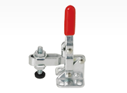
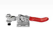
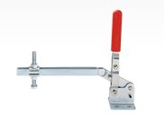
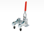
MISUMI toggle clamp
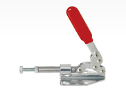
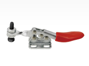
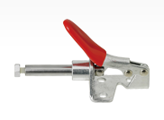
MISUMI offers toggle clamps of various shapes, including underside holding type (vertical/horizontal handle type) and horizontal drive orientation type.
Vertical type
Horizontal drive orientation type
Horizontal type
Level type
Long handle
Long arm
Forked type
PDF list
Payment Method
- Credit Card
- PayPal
- Bank Transfer
Social Media
MISUMI Contact
Copyright © MISUMI Corporation All Rights Reserved.