(!)Due to Microsoft's end of support for Internet Explorer 11 on 15/06/2022, this site does not support the recommended environment.
Instead, please kindly use other browsers like Google Chrome, Microsoft Edge or Mozilla Firefox.
50,000 Stock items for Same Day Ship Out.
All Categories
Categories
- Automation Components
A wide variety of standard and configurable components for factory automation engineers in industries such as automotive, semiconductor, packaging, medical and many more.
- Linear Motion
- Rotary Motion
- Connecting Parts
- Rotary Power Transmission
- Motors
- Conveyors & Material Handling
- Locating, Positioning, Jigs & Fixtures
- Inspection
- Sensors, Switches
- Pneumatics, Hydraulics
- Vacuum Components
- Hydraulic Equipment
- Discharging / Painting Devices
- Pipe, Tubes, Hoses & Fittings
- Modules, Units
- Heaters, Temperature Control
- Framing & Support
- Casters, Leveling Mounts, Posts
- Doors, Cabinet Hardware
- Springs, Shock Absorbers
- Adjusting, Fastening, Magnets
- Antivibration, Soundproofing Materials, Safety Products
- Fasteners
A good selection of accessories such as screws, bolts, washers and nuts that you may need for your daily engineering usage.
- Materials
Browse industrial materials ranging from heat insulating plates, sponges, to metal and plastic materials in different sizes to meet your various applications.
- Wiring Components
A wide variety of wiring parts for connecting and protecting control and PC parts including Connectors, Cables, Electric Wires, Crimping Terminals and more.
- LAN Cables / Industrial Network Cables
- Cables by Application
- Cables with Connectors
- RS232 / Personal Computers / AV Cables
- Wires/Cables
- Connectors (General Purpose)
- Crimp Terminals
- Zip Ties
- Cable Glands
- Cable Bushings/Clips/Stickers
- Screws/Spacers
- Cable Accessories
- Tubes
- Protection Tubes
- Ducts/Wiremolds
- General Purpose Tools
- Dedicated Tools
- Soldering Supplies
- Electrical & Controls
A wide variety of controls and PC parts for electrical engineers including Controls, Powers, PC parts and more.
- Cutting Tools
A wide variety of cutting tools for many uses and work materials including End Mills, Drills, Cutters, Reamers, Turning Tools and more.
- Carbide End Mills
- HSS End Mills
- Milling Cutter Inserts/Holders
- Customized Straight Blade End Mills
- Dedicated Cutters
- Turning Tools
- Drill Bits
- Screw-Hole-Related Tools
- Reamers
- Chamfering / Centering Tools
- Fixtures Related to Cutting Tools
- Step Drills
- Hole Saws
- Clean Key Cutters
- Core Drills (Tip Tools)
- Magnetic Drilling Machine Cutters
- Drill Bits for Electric Drilling Machines
- Woodworking Drill Cutters
- Drills for Concrete
- Processing Tools
A wide variety of tools and supplies used in processing including Machine Tools, Measurement Tools, Grinding and Polishing Supplies and more.
- Material Handling & Storage
A wide variety of goods used in shipment, material handling and warehouse including Tape supplies, Stretch film, Truck, Shelf, Crane and more.
- Tape Supplies
- Cushioning Materials
- Stretch Films
- Cardboard
- Plastic Bags
- PP Bands
- Magic Tapes / Tying Belts
- Rubber Bands
- Strings/Ropes
- Cable Ties
- Tags
- Labelers
- Unpacking Cutters
- Packing Support Equipment
- Cloth Sheets for Packing
- Conveyance/Dolly Carts
- Tool Wagons
- Tool Cabinets / Container Racks
- Lifters / Hand Pallets
- Container Pallets
- Storage Supplies
- Shelves/Racks
- Work Benches
- Suspended Clamps/Suspended Belts
- Jack Winches
- Chain Block Cranes
- Bottles/Containers
- Bicycle Storage Area
- Safety & General Supplies
A large variety of goods for every kind of factories and offices including Protection items, Cleaning supplies, sanitations, office supplies and more.
- Lab & Clean Room Supplies
A large variety of items used in R&D and Clean Room including research Equipment, Laboratory Essentials, Analysis Supplies, Clean Environment-Related Equipment and more.
- Press Die Components
Choose from thousands of standard stamping die components including Punch & Die, Gas Springs, Guide Components, Coil Springs and many more.
- Plastic Mold Components
Browse our wide variety of mold components including Ejector Pins, Sleeves, Leader Components, Sprue Bushings and many more.
- Ejector Pins
- Sleeves, Center Pins
- Core Pins
- Sprue bushings, Gates, and other components
- Date Mark Inserts, Recycle Mark Inserts, Pins with Gas Vent
- Undercut, Plates
- Leader Components, Components for Ejector Space
- Mold Opening Controllers
- Cooling or Heating Components
- Accessories, Others
- Components of Large Mold, Die Casting
- Injection Molding Components
Browse our injection molding components including Heating Items, Couplers, Hoses and more.
- Injection Molding Machine Products
- Accessories of Equipment
- Auxiliary Equipment
- Air Nippers
- Air Cylinders
- Air Chuck for Runner
- Chuck Board Components
- Frames
- Suction Components
- Parallel Air Chuck
- Special Air Chuck
- Chemical for Injection Molding
- Mold Maintenance
- Heating Items
- Heat Insulation Sheets
- Couplers, Plugs, One-touch Joints
- Tubes, Hoses, Peripheral Components
Search by Application
Brands


- Please be informed that our office is closed during the upcoming Labour Day Holiday in 2024. We would also like to inform you that there may be a potential delay in response/shipment from the supplier due to the Japan Golden Week holiday which falls from 29th April to 6th May 2024. Click here for details.
- Please Note our New Address (effective April 1, 2024): 331 North Bridge Rd, #05-01 Odeon 331, Singapore 188720.
SYSMAC CJ series CJ2M pulse I/O block
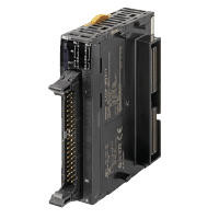
SYSMAC CJ Series CJ2M Pulse I/O Block
Part Number
Configured Part Number is shown.
CJ Series CJ2M CPU Unit, Pulse I/O Block Specifications
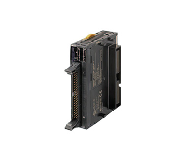
CJ2M-MD21□ external appearance
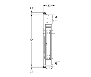
CJ2M-MD211/MD212 dimensional outline drawings, Units: mm
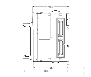
CJ2M-MD211/MD212 dimensional outline drawings, Units: mm
Features
- Improved basic computation performance such as a reduced LD command execution time of 40 ns and a SIN computation time of 0.86 μs. Faster function block calls as well.
- Optional pulse I/O modules (maximum of 2) can be mounted to enable positioning functions for up to four axes. Supports 4-point high-speed counters and 8-point interrupt inputs.
(CJ2M CPU Unit Ver. 2.0 or later) - Provides a dedicated storage area for function blocks, reducing the user program area usage amount, even with structured or parts-oriented programming using function blocks.
Performance Specifications
| Item | Performance Description | ||
|---|---|---|---|
| Pulse I/O | I/O Block Format | Model CJ2M-MD211 (sink output type) Model CJ2M-MD212 (source output type) | |
| External Interface | MIL 40-Pin Connector | ||
| Input | Can be used for general purpose input, interrupt input, quick response input and high-speed counter input (by switching the terminal function in the PLC system settings) Input method: Line driver input or 24 V DC input (switch using wiring) | ||
| General Purpose Input | Max. 20 points (10 points per pulse I/O block) Input time constant: Selectable in PLC system settings (0, 0.5, 1, 2, 4, 8, 16, 32 ms), default 8 ms | ||
| Interrupt Input, Quick Response Input | Max. 8 points (4 points per pulse I/O block) Input signal minimum pulse width: 30 μs min. | ||
| High Speed Counter Input | Max. 4 points (2 points per pulse I/O block) Input method: phase difference (multiplication by 4) pulse, pulse + direction, up/down pulse, increment pulse Maximum response frequency: 50 kHz for differential phases or 100 kHz for single phase Value range modes: linear mode, circular (ring) mode Count value: 32 bits Counter reset: Phase Z + software reset or software reset Control method: target-value comparison or range comparison Gate function: supported | ||
| Output | Can be used for general purpose output, pulse output and PWM output (by switching the terminal function in the PLC system settings) Output method: sinking or sourcing transistor outputs (the method is determined by the pulse I/O module model) | ||
| General-Purpose Output | Max. 12 points (6 points per pulse I/O block) | ||
| Pulse Output | Max. 4 points (2 points per pulse I/O block) Output method: CW/CCW or pulse + direction (the method is determined by the I/O wiring and the instructions used in the ladder program) Output frequency: 1 pps to 100 kpps (in increments of 1 pps) Output mode: continuous mode (for speed control) or independent mode (for position control) Output pulses: relative coordinates: 0000 0000 to 7FFF FFFF hex (0 to 2,147,483,647 pulses Absolute coordinates: 8000 0000 to 7FFF FFFF hex (−2,147,483,648 to 2,147,483,647) Acceleration/deceleration curves: linear or S-curve Origin search function: supported | ||
| PWM Output | Max. 4 points (2 points per pulse I/O block) Output frequency: 0.1 to 6,553.5 Hz (in 0.1-Hz increments) or 1 to 32,800 Hz (in 1-Hz increments) Duty ratio: 0.0% to 100.0% (in 0.1% increments) | ||
Function Specifications
| Function | Function Description | ||
|---|---|---|---|
| Pulse I/O Function | Input Function | General Purpose Input | Input signals are read during I/O refreshing and stored in I/O memory |
| Interrupt Input | An interrupt task can be started when an input signal turns ON or turns OFF | ||
| Quick Response Input | Input signals that are shorter than the cycle time are read and stored in I/O memory | ||
| High Speed Counter Input | High-speed pulse signals are counted. Interrupt tasks can also be started | ||
| Output Function | General-Purpose Output | The status of I/O memory is output during I/O refreshing | |
| Pulse Output | A pulse signal is output with the specified frequency and number of pulses at a fixed duty ratio (50%) | ||
| PWM Output | A pulse signal is output at the specified duty ratio | ||
| Origin Search Function | The origin point of the machine is determined according to the specified origin search parameters while actually outputting pulses and using the origin and origin proximity input signals as conditions (pulse inputs and outputs are also used for this function) | ||
| Interrupt Function | Input Interrupt Function | A task is started for an interrupt input from a pulse I/O module or for a high-speed counter input | |
| Input Interrupt | Interrupt tasks are executed when the interrupt input turns from OFF→ON or ON→OFF Direct mode: An interrupt task is executed each time an input signal changes Counter mode: Changes in the input signal are counted up or down and the interrupt task is executed when the counter counts up (the maximum response frequency is 3 kHz) | ||
| High Speed Counter Interrupt | An interrupt task is executed when preset comparison conditions for a high-speed counter are met Target-value comparison: The interrupt task is executed when the count matches a specified value. Range comparison: The interrupt task is executed when the count enters or leaves a specified range of values | ||
| Part Number |
|---|
| CJ2M-MD211 |
| CJ2M-MD212 |
| Part Number | Standard Unit Price | Minimum order quantity | Volume Discount | Days to Ship | Representative Standard |
|---|---|---|---|---|---|
SGD 420.32 | 1 Piece(s) | 4 Day(s) or more | CE / UL / CSA | ||
SGD 420.32 | 1 Piece(s) | 4 Day(s) or more | CE / UL / CUL / CSA |
Loading...
Basic Information
| Number Of Inputs | 10 | Number of Outputs | 6 | Output Format | Transistor / sync output |
|---|---|---|---|---|---|
| Connection Terminal | Connector | Current Consumption(A) | 0.08 | Name | Pulse I/O Block |
- The specifications and dimensions of some parts may not be fully covered. For exact details, refer to manufacturer catalogs .
Tech Support
- Factory Automation, Electronics, Tools, & MRO (Maintenance, Repair and Operations)
- Tel:(65) 6733 7211 / FAX:(65) 6733 0211
- 9:00am - 6:00pm (Monday - Friday)
- Technical Inquiry
Payment Method
- Credit Card
- PayPal
- Bank Transfer
Social Media
MISUMI Contact
Copyright © MISUMI Corporation All Rights Reserved.
How can we improve?
How can we improve?