(!)Due to Microsoft's end of support for Internet Explorer 11 on 15/06/2022, this site does not support the recommended environment.
Instead, please kindly use other browsers like Google Chrome, Microsoft Edge or Mozilla Firefox.
50,000 Stock items for Same Day Ship Out.
All Categories
Categories
- Automation Components
A wide variety of standard and configurable components for factory automation engineers in industries such as automotive, semiconductor, packaging, medical and many more.
- Linear Motion
- Rotary Motion
- Connecting Parts
- Rotary Power Transmission
- Motors
- Conveyors & Material Handling
- Locating, Positioning, Jigs & Fixtures
- Inspection
- Sensors, Switches
- Pneumatics, Hydraulics
- Vacuum Components
- Hydraulic Equipment
- Discharging / Painting Devices
- Pipe, Tubes, Hoses & Fittings
- Modules, Units
- Heaters, Temperature Control
- Framing & Support
- Casters, Leveling Mounts, Posts
- Doors, Cabinet Hardware
- Springs, Shock Absorbers
- Adjusting, Fastening, Magnets
- Antivibration, Soundproofing Materials, Safety Products
- Fasteners
A good selection of accessories such as screws, bolts, washers and nuts that you may need for your daily engineering usage.
- Materials
Browse industrial materials ranging from heat insulating plates, sponges, to metal and plastic materials in different sizes to meet your various applications.
- Wiring Components
A wide variety of wiring parts for connecting and protecting control and PC parts including Connectors, Cables, Electric Wires, Crimping Terminals and more.
- LAN Cables / Industrial Network Cables
- Cables by Application
- Cables with Connectors
- RS232 / Personal Computers / AV Cables
- Wires/Cables
- Connectors (General Purpose)
- Crimp Terminals
- Zip Ties
- Cable Glands
- Cable Bushings/Clips/Stickers
- Screws/Spacers
- Cable Accessories
- Tubes
- Protection Tubes
- Ducts/Wiremolds
- General Purpose Tools
- Dedicated Tools
- Soldering Supplies
- Electrical & Controls
A wide variety of controls and PC parts for electrical engineers including Controls, Powers, PC parts and more.
- Cutting Tools
A wide variety of cutting tools for many uses and work materials including End Mills, Drills, Cutters, Reamers, Turning Tools and more.
- Carbide End Mills
- HSS End Mills
- Milling Cutter Inserts/Holders
- Customized Straight Blade End Mills
- Dedicated Cutters
- Turning Tools
- Drill Bits
- Screw-Hole-Related Tools
- Reamers
- Chamfering / Centering Tools
- Fixtures Related to Cutting Tools
- Step Drills
- Hole Saws
- Clean Key Cutters
- Core Drills (Tip Tools)
- Magnetic Drilling Machine Cutters
- Drill Bits for Electric Drilling Machines
- Woodworking Drill Cutters
- Drills for Concrete
- Processing Tools
A wide variety of tools and supplies used in processing including Machine Tools, Measurement Tools, Grinding and Polishing Supplies and more.
- Material Handling & Storage
A wide variety of goods used in shipment, material handling and warehouse including Tape supplies, Stretch film, Truck, Shelf, Crane and more.
- Tape Supplies
- Cushioning Materials
- Stretch Films
- Cardboard
- Plastic Bags
- PP Bands
- Magic Tapes / Tying Belts
- Rubber Bands
- Strings/Ropes
- Cable Ties
- Tags
- Labelers
- Unpacking Cutters
- Packing Support Equipment
- Cloth Sheets for Packing
- Conveyance/Dolly Carts
- Tool Wagons
- Tool Cabinets / Container Racks
- Lifters / Hand Pallets
- Container Pallets
- Storage Supplies
- Shelves/Racks
- Work Benches
- Suspended Clamps/Suspended Belts
- Jack Winches
- Chain Block Cranes
- Bottles/Containers
- Bicycle Storage Area
- Safety & General Supplies
A large variety of goods for every kind of factories and offices including Protection items, Cleaning supplies, sanitations, office supplies and more.
- Lab & Clean Room Supplies
A large variety of items used in R&D and Clean Room including research Equipment, Laboratory Essentials, Analysis Supplies, Clean Environment-Related Equipment and more.
- Press Die Components
Choose from thousands of standard stamping die components including Punch & Die, Gas Springs, Guide Components, Coil Springs and many more.
- Plastic Mold Components
Browse our wide variety of mold components including Ejector Pins, Sleeves, Leader Components, Sprue Bushings and many more.
- Ejector Pins
- Sleeves, Center Pins
- Core Pins
- Sprue bushings, Gates, and other components
- Date Mark Inserts, Recycle Mark Inserts, Pins with Gas Vent
- Undercut, Plates
- Leader Components, Components for Ejector Space
- Mold Opening Controllers
- Cooling or Heating Components
- Accessories, Others
- Components of Large Mold, Die Casting
- Injection Molding Components
Browse our injection molding components including Heating Items, Couplers, Hoses and more.
- Injection Molding Machine Products
- Accessories of Equipment
- Auxiliary Equipment
- Air Nippers
- Air Cylinders
- Air Chuck for Runner
- Chuck Board Components
- Frames
- Suction Components
- Parallel Air Chuck
- Special Air Chuck
- Chemical for Injection Molding
- Mold Maintenance
- Heating Items
- Heat Insulation Sheets
- Couplers, Plugs, One-touch Joints
- Tubes, Hoses, Peripheral Components
Search by Application
Brands


- Please be informed that our office is closed during the upcoming Labour Day Holiday in 2024. We would also like to inform you that there may be a potential delay in response/shipment from the supplier due to the Japan Golden Week holiday which falls from 29th April to 6th May 2024. Click here for details.
- Please Note our New Address (effective April 1, 2024): 331 North Bridge Rd, #05-01 Odeon 331, Singapore 188720.
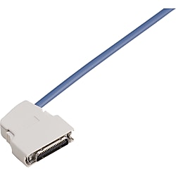
Cable with IEEE1284 half-pitch (MDR) connector EMI countermeasure angle (using 3M connector)
Click this image to zoom it.
Move the mouse over the image to zoom
Most Versatile Half-Pitch Connector Harness
- Space-saving
- PLC
- EMI Countermeasure
- Pressure Welding
- Small Diameter

● A cable with IEEE1284 connector that supports various models of control equipment such as servo drivers. Twisted pair cable is shielded as an EMI countermeasure.
● The connector has an angle model hood and the cable is thin, which allows it to conserve space.
● 35% thinner than conventional cables for easier laying of cables.

Wiring and Wire Color Page >>Click here.
Component Page >>Click here.
Part Number
Configured Part Number is shown.
Specifications

| Specified Length (m) | ~ 0.9 | 1 ~ 4 | 4.1 ~ 50 |
| Tolerance | +20mm | +50mm | + 3% of Specified Length |
| Part Number |
|---|
| SHPT-HA-A-20-[0.2-50/0.1] |
| SHPT-HA-A-36-[0.2-50/0.1] |
| SHPT-HA-SB-20-[0.2-50/0.1] |
| SHPT-HA-SB-36-[0.2-50/0.1] |
| SHPT-HAH-A-20-[0.2-50/0.1] |
| SHPT-HAH-A-36-[0.2-50/0.1] |
| SHPT-HAH-SB-20-[0.2-50/0.1] |
| SHPT-HAH-SB-36-[0.2-50/0.1] |
| SHPT-HAT-A-20-[0.2-50/0.1] |
| SHPT-HAT-A-36-[0.2-50/0.1] |
| SHPT-HAT-SB-20-[0.2-50/0.1] |
| SHPT-HAT-SB-36-[0.2-50/0.1] |
| SHPT-HAU-A-20-[0.2-50/0.1] |
| SHPT-HAU-A-36-[0.2-50/0.1] |
| SHPT-HAU-SB-20-[0.2-50/0.1] |
| SHPT-HAU-SB-36-[0.2-50/0.1] |
| SHPT-HAUC-A-20-[0.2-50/0.1] |
| SHPT-HAUC-A-36-[0.2-50/0.1] |
| SHPT-HAUC-SB-20-[0.2-50/0.1] |
| SHPT-HAUC-SB-36-[0.2-50/0.1] |
| SHPT-HAUJ-A-20-[0.2-50/0.1] |
| SHPT-HAUJ-A-36-[0.2-50/0.1] |
| SHPT-HAUJ-SB-20-[0.2-50/0.1] |
| SHPT-HAUJ-SB-36-[0.2-50/0.1] |
| SHPT-HAY-A-20-[0.2-50/0.1] |
| SHPT-HAY-A-36-[0.2-50/0.1] |
| SHPT-HAY-SB-20-[0.2-50/0.1] |
| SHPT-HAY-SB-36-[0.2-50/0.1] |
| SHPT-HB-A-20-[0.2-50/0.1] |
| SHPT-HB-A-36-[0.2-50/0.1] |
| SHPT-HB-SB-20-[0.2-50/0.1] |
| SHPT-HB-SB-36-[0.2-50/0.1] |
| SHPT-HBH-A-20-[0.2-50/0.1] |
| SHPT-HBH-A-36-[0.2-50/0.1] |
| SHPT-HBH-SB-20-[0.2-50/0.1] |
| SHPT-HBH-SB-36-[0.2-50/0.1] |
| SHPT-HBT-A-20-[0.2-50/0.1] |
| SHPT-HBT-A-36-[0.2-50/0.1] |
| SHPT-HBT-SB-20-[0.2-50/0.1] |
| SHPT-HBT-SB-36-[0.2-50/0.1] |
| SHPT-HBU-A-20-[0.2-50/0.1] |
| SHPT-HBU-A-36-[0.2-50/0.1] |
| SHPT-HBU-SB-20-[0.2-50/0.1] |
| SHPT-HBU-SB-36-[0.2-50/0.1] |
| SHPT-HBUC-A-20-[0.2-50/0.1] |
| SHPT-HBUC-A-36-[0.2-50/0.1] |
| SHPT-HBUC-SB-20-[0.2-50/0.1] |
| SHPT-HBUC-SB-36-[0.2-50/0.1] |
| SHPT-HBUJ-A-20-[0.2-50/0.1] |
| SHPT-HBUJ-A-36-[0.2-50/0.1] |
| SHPT-HBUJ-SB-20-[0.2-50/0.1] |
| SHPT-HBUJ-SB-36-[0.2-50/0.1] |
| SHPT-HBY-A-20-[0.2-50/0.1] |
| SHPT-HBY-A-36-[0.2-50/0.1] |
| SHPT-HBY-SB-20-[0.2-50/0.1] |
| SHPT-HBY-SB-36-[0.2-50/0.1] |
| Part Number | Standard Unit Price | Minimum order quantity | Volume Discount | Days to Ship | CN2 | Number Of Cores | Shield | Cable color | Cable wiring direction (CN1 connector) | Cable type | Connector 2 details | Specified Length (m) |
|---|---|---|---|---|---|---|---|---|---|---|---|---|
- | 1 Piece(s) | 5 Day(s) or more | Cut off | 20 | 1 Layer | Navy | Right Side | A | - | 0.2 ~ 50 | ||
- | 1 Piece(s) | 5 Day(s) or more | Cut off | 36 | 1 Layer | Navy | Right Side | A | - | 0.2 ~ 50 | ||
- | 1 Piece(s) | 5 Day(s) or more | Cut off | 20 | 2 Layer | Black | Right Side | SB | - | 0.2 ~ 50 | ||
- | 1 Piece(s) | 5 Day(s) or more | Cut off | 36 | 2 Layer | Black | Right Side | SB | - | 0.2 ~ 50 | ||
- | 1 Piece(s) | 5 Day(s) or more | Male | 20 | 1 Layer | Navy | Right Side | A | - | 0.2 ~ 50 | ||
- | 1 Piece(s) | 5 Day(s) or more | Male | 36 | 1 Layer | Navy | Right Side | A | - | 0.2 ~ 50 | ||
- | 1 Piece(s) | 5 Day(s) or more | Male | 20 | 2 Layer | Black | Right Side | SB | - | 0.2 ~ 50 | ||
- | 1 Piece(s) | 5 Day(s) or more | Male | 36 | 2 Layer | Black | Right Side | SB | - | 0.2 ~ 50 | ||
- | 1 Piece(s) | 5 Day(s) or more | Discrete wire | 20 | 1 Layer | Navy | Right Side | A | - | 0.2 ~ 50 | ||
- | 1 Piece(s) | 5 Day(s) or more | Discrete wire | 36 | 1 Layer | Navy | Right Side | A | - | 0.2 ~ 50 | ||
- | 1 Piece(s) | 5 Day(s) or more | Discrete wire | 20 | 2 Layer | Black | Right Side | SB | - | 0.2 ~ 50 | ||
- | 1 Piece(s) | 5 Day(s) or more | Discrete wire | 36 | 2 Layer | Black | Right Side | SB | - | 0.2 ~ 50 | ||
- | 1 Piece(s) | 5 Day(s) or more | Fusion | 20 | 1 Layer | Navy | Right Side | A | - | 0.2 ~ 50 | ||
- | 1 Piece(s) | 5 Day(s) or more | Fusion | 36 | 1 Layer | Navy | Right Side | A | - | 0.2 ~ 50 | ||
- | 1 Piece(s) | 5 Day(s) or more | Fusion | 20 | 2 Layer | Black | Right Side | SB | - | 0.2 ~ 50 | ||
- | 1 Piece(s) | 5 Day(s) or more | Fusion | 36 | 2 Layer | Black | Right Side | SB | - | 0.2 ~ 50 | ||
- | 1 Piece(s) | 5 Day(s) or more | Fusion | 20 | 1 Layer | Navy | Right Side | A | Fusion Surface Staggered Arrangement | 0.2 ~ 50 | ||
- | 1 Piece(s) | 5 Day(s) or more | Fusion | 36 | 1 Layer | Navy | Right Side | A | Fusion Surface Staggered Arrangement | 0.2 ~ 50 | ||
- | 1 Piece(s) | 5 Day(s) or more | Fusion | 20 | 2 Layer | Black | Right Side | SB | Fusion Surface Staggered Arrangement | 0.2 ~ 50 | ||
- | 1 Piece(s) | 5 Day(s) or more | Fusion | 36 | 2 Layer | Black | Right Side | SB | Fusion Surface Staggered Arrangement | 0.2 ~ 50 | ||
- | 1 Piece(s) | 5 Day(s) or more | Fusion | 20 | 1 Layer | Navy | Right Side | A | Fusion Surface In-Line Arrangement | 0.2 ~ 50 | ||
- | 1 Piece(s) | 5 Day(s) or more | Fusion | 36 | 1 Layer | Navy | Right Side | A | Fusion Surface In-Line Arrangement | 0.2 ~ 50 | ||
- | 1 Piece(s) | 5 Day(s) or more | Fusion | 20 | 2 Layer | Black | Right Side | SB | Fusion Surface In-Line Arrangement | 0.2 ~ 50 | ||
- | 1 Piece(s) | 5 Day(s) or more | Fusion | 36 | 2 Layer | Black | Right Side | SB | Fusion Surface In-Line Arrangement | 0.2 ~ 50 | ||
- | 1 Piece(s) | 5 Day(s) or more | Y terminal | 20 | 1 Layer | Navy | Right Side | A | - | 0.2 ~ 50 | ||
- | 1 Piece(s) | 5 Day(s) or more | Y terminal | 36 | 1 Layer | Navy | Right Side | A | - | 0.2 ~ 50 | ||
- | 1 Piece(s) | 5 Day(s) or more | Y terminal | 20 | 2 Layer | Black | Right Side | SB | - | 0.2 ~ 50 | ||
- | 1 Piece(s) | 5 Day(s) or more | Y terminal | 36 | 2 Layer | Black | Right Side | SB | - | 0.2 ~ 50 | ||
- | 1 Piece(s) | 5 Day(s) or more | Cut off | 20 | 1 Layer | Navy | Left Side | A | - | 0.2 ~ 50 | ||
- | 1 Piece(s) | 5 Day(s) or more | Cut off | 36 | 1 Layer | Navy | Left Side | A | - | 0.2 ~ 50 | ||
- | 1 Piece(s) | 5 Day(s) or more | Cut off | 20 | 2 Layer | Black | Left Side | SB | - | 0.2 ~ 50 | ||
- | 1 Piece(s) | 5 Day(s) or more | Cut off | 36 | 2 Layer | Black | Left Side | SB | - | 0.2 ~ 50 | ||
- | 1 Piece(s) | 5 Day(s) or more | Male | 20 | 1 Layer | Navy | Left Side | A | - | 0.2 ~ 50 | ||
- | 1 Piece(s) | 5 Day(s) or more | Male | 36 | 1 Layer | Navy | Left Side | A | - | 0.2 ~ 50 | ||
- | 1 Piece(s) | 5 Day(s) or more | Male | 20 | 2 Layer | Black | Left Side | SB | - | 0.2 ~ 50 | ||
- | 1 Piece(s) | 5 Day(s) or more | Male | 36 | 2 Layer | Black | Left Side | SB | - | 0.2 ~ 50 | ||
- | 1 Piece(s) | 5 Day(s) or more | Discrete wire | 20 | 1 Layer | Navy | Left Side | A | - | 0.2 ~ 50 | ||
- | 1 Piece(s) | 5 Day(s) or more | Discrete wire | 36 | 1 Layer | Navy | Left Side | A | - | 0.2 ~ 50 | ||
- | 1 Piece(s) | 5 Day(s) or more | Discrete wire | 20 | 2 Layer | Black | Left Side | SB | - | 0.2 ~ 50 | ||
- | 1 Piece(s) | 5 Day(s) or more | Discrete wire | 36 | 2 Layer | Black | Left Side | SB | - | 0.2 ~ 50 | ||
- | 1 Piece(s) | 5 Day(s) or more | Fusion | 20 | 1 Layer | Navy | Left Side | A | - | 0.2 ~ 50 | ||
- | 1 Piece(s) | 5 Day(s) or more | Fusion | 36 | 1 Layer | Navy | Left Side | A | - | 0.2 ~ 50 | ||
- | 1 Piece(s) | 5 Day(s) or more | Fusion | 20 | 2 Layer | Black | Left Side | SB | - | 0.2 ~ 50 | ||
- | 1 Piece(s) | 5 Day(s) or more | Fusion | 36 | 2 Layer | Black | Left Side | SB | - | 0.2 ~ 50 | ||
- | 1 Piece(s) | 5 Day(s) or more | Fusion | 20 | 1 Layer | Navy | Left Side | A | Fusion Surface Staggered Arrangement | 0.2 ~ 50 | ||
- | 1 Piece(s) | 5 Day(s) or more | Fusion | 36 | 1 Layer | Navy | Left Side | A | Fusion Surface Staggered Arrangement | 0.2 ~ 50 | ||
- | 1 Piece(s) | 5 Day(s) or more | Fusion | 20 | 2 Layer | Black | Left Side | SB | Fusion Surface Staggered Arrangement | 0.2 ~ 50 | ||
- | 1 Piece(s) | 5 Day(s) or more | Fusion | 36 | 2 Layer | Black | Left Side | SB | Fusion Surface Staggered Arrangement | 0.2 ~ 50 | ||
- | 1 Piece(s) | 5 Day(s) or more | Fusion | 20 | 1 Layer | Navy | Left Side | A | Fusion Surface In-Line Arrangement | 0.2 ~ 50 | ||
- | 1 Piece(s) | 5 Day(s) or more | Fusion | 36 | 1 Layer | Navy | Left Side | A | Fusion Surface In-Line Arrangement | 0.2 ~ 50 | ||
- | 1 Piece(s) | 5 Day(s) or more | Fusion | 20 | 2 Layer | Black | Left Side | SB | Fusion Surface In-Line Arrangement | 0.2 ~ 50 | ||
- | 1 Piece(s) | 5 Day(s) or more | Fusion | 36 | 2 Layer | Black | Left Side | SB | Fusion Surface In-Line Arrangement | 0.2 ~ 50 | ||
- | 1 Piece(s) | 5 Day(s) or more | Y terminal | 20 | 1 Layer | Navy | Left Side | A | - | 0.2 ~ 50 | ||
- | 1 Piece(s) | 5 Day(s) or more | Y terminal | 36 | 1 Layer | Navy | Left Side | A | - | 0.2 ~ 50 | ||
- | 1 Piece(s) | 5 Day(s) or more | Y terminal | 20 | 2 Layer | Black | Left Side | SB | - | 0.2 ~ 50 | ||
- | 1 Piece(s) | 5 Day(s) or more | Y terminal | 36 | 2 Layer | Black | Left Side | SB | - | 0.2 ~ 50 |
Loading...
Compatible Manufacturers and Series Names
| Manufacturer Name | Series Name |
|---|---|
| AMP | CHAMP 50 |
| Hirose Electric Co., Ltd. | DXM (Note) |
| Japan Aviation Electronics Industry, Ltd. | TX10 |
| Honda Tsushin Kogyo Co., Ltd. | NPC |
| DDK Ltd. | DHA |
| Fujitsu Limited | 240R Type |
| Yamaichi Electronics Co., Ltd. | NCS/NCP |
(Note) Please note that these are not compatible with the DX Series by Hirose Electric Co., Ltd.
Contact Arrangement Diagram

Connector x Hood Combination Table
| EMI Countermeasure Plastic Hood One-touch Lock | EMI Countermeasure Metal Hood One-touch Lock | EMI Countermeasure Plastic Hood Screw Fastening | General-purpose Plastic Hood Screw Fastening | General-purpose Plastic Hood One-touch Lock | |||
|---|---|---|---|---|---|---|---|
| 103** -3210-00 | 103** -A200-00 | 103** -52S0-00S | 103** -52A0-008 | 103** -52F0-008 | |||
| Male | Pressure Welding Type Connector | 101** -6000EL | ○ | ○ | ○ (Except 68-core) | ○ (Except 68-core) | ○ (Except 68-core) |
| Female | Solder Type Connector | 101** -3000PE | x | x | ○ | ○ | ○ |
| Pressure Welding Type Panel Mount | 102** -0200EL | x | x | x | x | x | |
・Connectors can be coupled if they have the same core numbers and are a combination of male <--> female.
Compatible Wire
| Type | AWG |
|---|---|
| Pressure Welding Type Male Connector | AWG28 stranded wires or 0.08 mm2 stranded wires (Coating OD 0.70 mm or less) and navy fixed type cables can be used. * Flat cables cannot be used. (Note) |
| Solder Type Male Connector | AWG24 ~ 30 or 0.2 mm2 ~ 0.05 mm2 (Flat cables cannot be used.)* Pay attention to the finished OD of the cables. |
| Pressure Welding Type Panel Mount (Female) | AWG28 or 0.08 mm2, 1.27 mm Pitch Flat Cables (Loose wires cannot be used.)* |
Rating
| Item | Specification | Conditions |
|---|---|---|
| Current | 0.5 A or less | Allowable current between coupled contacts |
| Voltage | 150 VAC / 200 VDC or less | Refers to the maximum DC or AC voltage (effective value) that can be continuously applied under the rated ambient temperature |
| Ambient Temperature | -55°C ~ +85°C | Refers to the temperature range that can be used continuously under maximum load conditions |
Electrical Properties
| Item | Characteristics | Conditions |
|---|---|---|
| Contact Resistance | Initial value of 35 mΩ or less For contact after mechanical testing or environmental testing increased resistance value must be 25 mΩ or less |
Includes bulk resistance of contacts. 1.5 mA resistance measured current and 20 mV release voltage based on the voltage-drop testing method. (Based on combination with half pitch connectors by Sumitomo 3M) |
| Insulation Resistance | 500 MΩ or more | Apply 500 VDC between the adjoining contacts and measure the resistance after 1 min. |
| Voltage Resistance | No arc dielectric breakdown | Apply 500 VAC between the adjoining contacts for 1 min. Leakage current is 1 mA at the time of measurement. |
Mechanical Properties
| Item | Characteristics | Conditions |
|---|---|---|
| Contact Retention Force | 1 kg or more (Pressure welding type panel mount is 0.8 kg or more) |
Measure the contact retention force when tension is applied at the speed of 5 mm / min between the connector body and the installed contact. |
| Insertion and Extraction Force Per Single Pole | ・ Insertion Force: 150 g or less / Extraction Force: 40 g or more |
The total insertion / removal force for plug / panel mount insertion / removal applied to a single pole is adopted as the single-pole insertion / removal force. (Based on combination with plugs by Sumitomo 3M) Insertion / Extraction speed is 5 mm / min. |
| Vibration Test | 1) 1 μsec or less instantaneous disconnection 2) Meets electrical & mechanical properties |
10 ~ 55 HZ, insertion & extraction for 1 min, 1.52 mm amplitude or 10 G in XYZ directions for 2 hours each |
| Impact Test | 1) 1 μsec or less instantaneous disconnection 2) Meets electrical & mechanical properties |
50 G, 11 msec XYZ directions, 3 times each (18 times total) MIL-STD-202E201A |
| Solvent Resistance | 1) Indication is clear 2) Meets the electrical & mechanical properties |
3 min of ultrasonic cleaning in Freon 1-1-1 Trichloroethane solvent MIL-STD-202E213B |
| Durability | 1) Meets the electrical & mechanical properties However, initial values at insertion and extraction must be ±20% |
50 times of insertion and extraction (Speed at 360 ~ 600 times / hr.) MIL-STD-202E215 |
Environmental Resistance Properties
| Item | Test Conditions | Standards Compliance |
|---|---|---|
| Humidity Test | 10 Cycles (-10°C ~ +65°C, 95% RH) | MIL-STD-202E106D |
| Salt Spray Test | 35°C, 5% concentration, 48 hr. | MIL-STD-202E101D |
| Thermal Shock Test | 5 Cycles of -55°C --> +25°C --> +85°C --> +25°C | MIL-STD-202E107D |
| Humidity Test (Regulated Temperature) | 40°C, 95% RH, 96 hr. | MIL-STD-202E103D |
| High Temperature Life Test | 85°C, 1,000 hr., rated current x 110% rated current | MIL-STD-202E108D |
| H2S Gas | Concentration 3±1 PPM, 40°C, 70 ~ 85% RH, 96 hr. | JEIDA-25-1974 (Except for Solder Plug) |
Basic Information
| Connector type | IEEE | Connector manufacturer | Sumitomo 3M | Connector Shape | Angle |
|---|---|---|---|---|---|
| Machining Method | Pressure welding | Cable shape | Circular | Hood | EMI-compatible plastic |
| CN1 | Male | Cable rated voltage(V) | 30 | Cable standard (UL/CSA) | UL |
| Twisted pair | Included | AWG | 28 | Connector fastening method | One-touch |
| Notes | Please see the catalog for more information on mating surface and wiring direction. |
Specification/Dimensions
-
CN2
- Male
- Discrete wire
- Y terminal
- Cut off
- Fusion
-
Number Of Cores
-
Shield
- 1 Layer
- 2 Layer
-
Cable color
- Black
- Navy
-
Cable wiring direction (CN1 connector)
- Left Side
- Right Side
-
Cable type
- A
- SB
-
Connector 2 details
-
Specified Length(m)
Specify Alterations
- The specifications and dimensions of some parts may not be fully covered. For exact details, refer to manufacturer catalogs .
Tech Support
- Factory Automation, Electronics, Tools, & MRO (Maintenance, Repair and Operations)
- Tel:(65) 6733 7211 / FAX:(65) 6733 0211
- 9:00am - 6:00pm (Monday - Friday)
- Technical Inquiry
Payment Method
- Credit Card
- PayPal
- Bank Transfer
Social Media
MISUMI Contact
Copyright © MISUMI Corporation All Rights Reserved.
How can we improve?
How can we improve?