(!)Due to Microsoft's end of support for Internet Explorer 11 on 15/06/2022, this site does not support the recommended environment.
Instead, please kindly use other browsers like Google Chrome, Microsoft Edge or Mozilla Firefox.
50,000 Stock items for Same Day Ship Out.
All Categories
Categories
- Automation Components
A wide variety of standard and configurable components for factory automation engineers in industries such as automotive, semiconductor, packaging, medical and many more.
- Linear Motion
- Rotary Motion
- Connecting Parts
- Rotary Power Transmission
- Motors
- Conveyors & Material Handling
- Locating, Positioning, Jigs & Fixtures
- Inspection
- Sensors, Switches
- Pneumatics, Hydraulics
- Vacuum Components
- Hydraulic Equipment
- Discharging / Painting Devices
- Pipe, Tubes, Hoses & Fittings
- Modules, Units
- Heaters, Temperature Control
- Framing & Support
- Casters, Leveling Mounts, Posts
- Doors, Cabinet Hardware
- Springs, Shock Absorbers
- Adjusting, Fastening, Magnets
- Antivibration, Soundproofing Materials, Safety Products
- Fasteners
A good selection of accessories such as screws, bolts, washers and nuts that you may need for your daily engineering usage.
- Materials
Browse industrial materials ranging from heat insulating plates, sponges, to metal and plastic materials in different sizes to meet your various applications.
- Wiring Components
A wide variety of wiring parts for connecting and protecting control and PC parts including Connectors, Cables, Electric Wires, Crimping Terminals and more.
- LAN Cables / Industrial Network Cables
- Cables by Application
- Cables with Connectors
- RS232 / Personal Computers / AV Cables
- Wires/Cables
- Connectors (General Purpose)
- Crimp Terminals
- Zip Ties
- Cable Glands
- Cable Bushings/Clips/Stickers
- Screws/Spacers
- Cable Accessories
- Tubes
- Protection Tubes
- Ducts/Wiremolds
- General Purpose Tools
- Dedicated Tools
- Soldering Supplies
- Electrical & Controls
A wide variety of controls and PC parts for electrical engineers including Controls, Powers, PC parts and more.
- Cutting Tools
A wide variety of cutting tools for many uses and work materials including End Mills, Drills, Cutters, Reamers, Turning Tools and more.
- Carbide End Mills
- HSS End Mills
- Milling Cutter Inserts/Holders
- Customized Straight Blade End Mills
- Dedicated Cutters
- Turning Tools
- Drill Bits
- Screw-Hole-Related Tools
- Reamers
- Chamfering / Centering Tools
- Fixtures Related to Cutting Tools
- Step Drills
- Hole Saws
- Clean Key Cutters
- Core Drills (Tip Tools)
- Magnetic Drilling Machine Cutters
- Drill Bits for Electric Drilling Machines
- Woodworking Drill Cutters
- Drills for Concrete
- Processing Tools
A wide variety of tools and supplies used in processing including Machine Tools, Measurement Tools, Grinding and Polishing Supplies and more.
- Material Handling & Storage
A wide variety of goods used in shipment, material handling and warehouse including Tape supplies, Stretch film, Truck, Shelf, Crane and more.
- Tape Supplies
- Cushioning Materials
- Stretch Films
- Cardboard
- Plastic Bags
- PP Bands
- Magic Tapes / Tying Belts
- Rubber Bands
- Strings/Ropes
- Cable Ties
- Tags
- Labelers
- Unpacking Cutters
- Packing Support Equipment
- Cloth Sheets for Packing
- Conveyance/Dolly Carts
- Tool Wagons
- Tool Cabinets / Container Racks
- Lifters / Hand Pallets
- Container Pallets
- Storage Supplies
- Shelves/Racks
- Work Benches
- Suspended Clamps/Suspended Belts
- Jack Winches
- Chain Block Cranes
- Bottles/Containers
- Bicycle Storage Area
- Safety & General Supplies
A large variety of goods for every kind of factories and offices including Protection items, Cleaning supplies, sanitations, office supplies and more.
- Lab & Clean Room Supplies
A large variety of items used in R&D and Clean Room including research Equipment, Laboratory Essentials, Analysis Supplies, Clean Environment-Related Equipment and more.
- Press Die Components
Choose from thousands of standard stamping die components including Punch & Die, Gas Springs, Guide Components, Coil Springs and many more.
- Plastic Mold Components
Browse our wide variety of mold components including Ejector Pins, Sleeves, Leader Components, Sprue Bushings and many more.
- Ejector Pins
- Sleeves, Center Pins
- Core Pins
- Sprue bushings, Gates, and other components
- Date Mark Inserts, Recycle Mark Inserts, Pins with Gas Vent
- Undercut, Plates
- Leader Components, Components for Ejector Space
- Mold Opening Controllers
- Cooling or Heating Components
- Accessories, Others
- Components of Large Mold, Die Casting
- Injection Molding Components
Browse our injection molding components including Heating Items, Couplers, Hoses and more.
- Injection Molding Machine Products
- Accessories of Equipment
- Auxiliary Equipment
- Air Nippers
- Air Cylinders
- Air Chuck for Runner
- Chuck Board Components
- Frames
- Suction Components
- Parallel Air Chuck
- Special Air Chuck
- Chemical for Injection Molding
- Mold Maintenance
- Heating Items
- Heat Insulation Sheets
- Couplers, Plugs, One-touch Joints
- Tubes, Hoses, Peripheral Components
Search by Application
Brands


- Please be informed that our office is closed during the upcoming Labour Day Holiday in 2024. We would also like to inform you that there may be a potential delay in response/shipment from the supplier due to the Japan Golden Week holiday which falls from 29th April to 6th May 2024. Click here for details.
- Please Note our New Address (effective April 1, 2024): 331 North Bridge Rd, #05-01 Odeon 331, Singapore 188720.
Single Axis Robots E-MTH5 Screw Drive, Semi-Sealed Type(General Use)
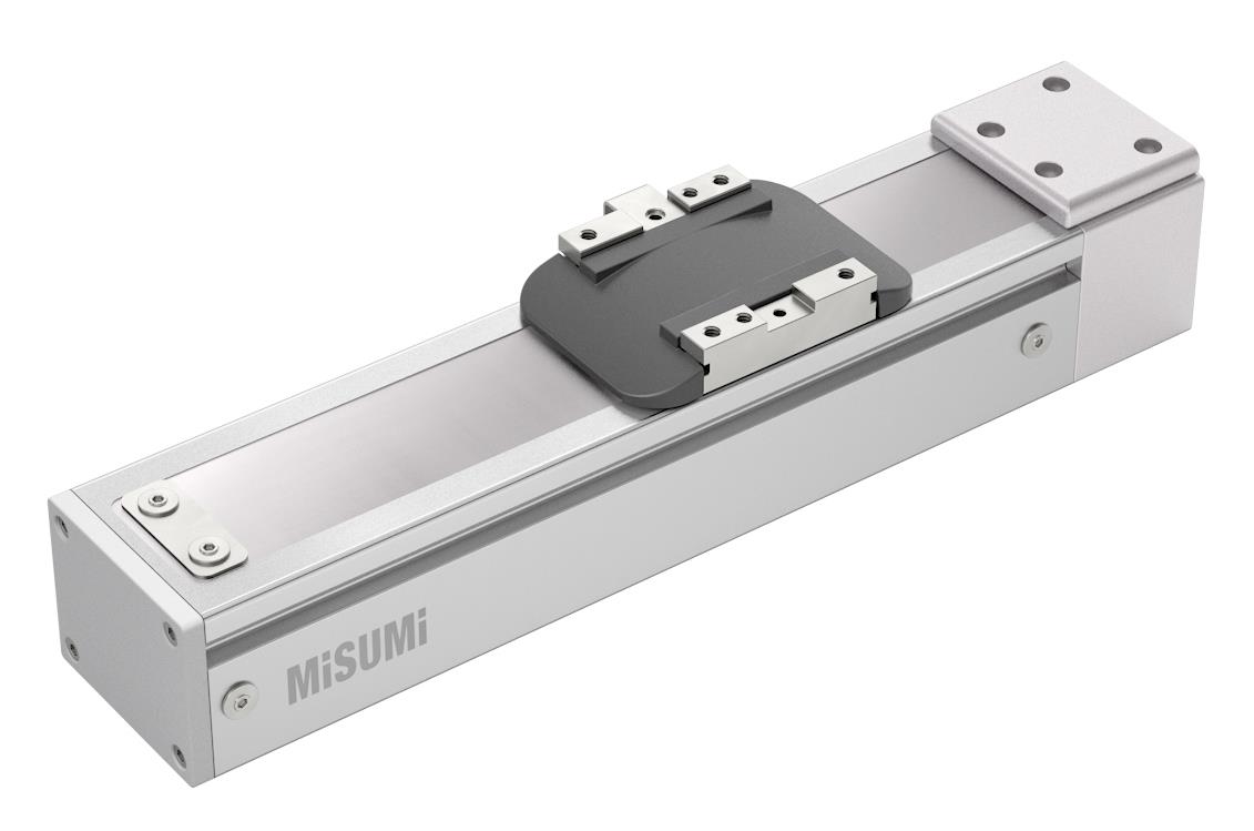
Economy series Aluminum Alloy Embedded Actuators E-MTH5 Series product only includes the main unit, not the driver, which must be purchased separately. The product comes with a sensor kit (3 sensors), for which only mounting direction needs to be selected.
(i)Caution
- The product does not come with a driver or motor, which must be purchased separately
- The product comes with a sensor kit, which is unnecessary to select
Part Number
Configured Part Number is shown.
Up to ±0.01 or less.
2. Small size and light weight
3. High precision ±0.01
4. High rigidity
5. Low noise
6. Complete set of fittings
■BC Motor Exposed
Dimension (mm), Mass (kg)
| Effective Stroke | 50 | 100 | 150 | 200 | 250 | 300 | 350 | 400 | 450 | 500 | 550 | 600 | 650 | 700 | 750 | 800 |
| L | 216 | 266 | 316 | 366 | 416 | 466 | 516 | 566 | 616 | 666 | 716 | 766 | 816 | 866 | 916 | 966 |
| A | 60 | 30 | 40 | 50 | 60 | 30 | 40 | 50 | 60 | 30 | 40 | 50 | 60 | 30 | 40 | 50 |
| M | 2 | 4 | 5 | 6 | 7 | 9 | 10 | 11 | 12 | 14 | 15 | 16 | 17 | 19 | 20 | 21 |
| N | 3 | 5 | 6 | 7 | 8 | 10 | 11 | 12 | 13 | 15 | 16 | 17 | 18 | 20 | 21 | 22 |
| KG | 1.56 | 1.71 | 1.85 | 2 | 2.14 | 2.29 | 2.44 | 2.58 | 2.73 | 2.87 | 3.02 | 3.17 | 3.31 | 3.46 | 3.6 | 3.75 |
■BM Motor On Lower Side
| Effective Stroke | 50 | 100 | 150 | 200 | 250 | 300 | 350 | 400 | 450 | 500 | 550 | 600 | 650 | 700 | 750 | 800 |
| L | 208 | 258 | 308 | 358 | 408 | 458 | 508 | 558 | 608 | 658 | 708 | 758 | 808 | 858 | 908 | 958 |
| A | 60 | 30 | 40 | 50 | 60 | 30 | 40 | 50 | 60 | 30 | 40 | 50 | 60 | 30 | 40 | 50 |
| M | 2 | 4 | 5 | 6 | 7 | 9 | 10 | 11 | 12 | 14 | 15 | 16 | 17 | 19 | 20 | 21 |
| N | 3 | 5 | 6 | 7 | 8 | 10 | 11 | 12 | 13 | 15 | 16 | 17 | 18 | 20 | 21 | 22 |
| KG | 1.66 | 1.81 | 1.95 | 2.1 | 2.24 | 2.39 | 2.54 | 2.68 | 2.83 | 2.97 | 3.12 | 3.27 | 3.41 | 3.56 | 3.7 | 3.85 |
■BR Motor On Right Side
Dimension (mm), Mass (kg)
| Effective Stroke | 50 | 100 | 150 | 200 | 250 | 300 | 350 | 400 | 450 | 500 | 550 | 600 | 650 | 700 | 750 | 800 |
| L | 208 | 258 | 308 | 358 | 408 | 458 | 508 | 558 | 608 | 658 | 708 | 758 | 808 | 858 | 908 | 958 |
| A | 60 | 30 | 40 | 50 | 60 | 30 | 40 | 50 | 60 | 30 | 40 | 50 | 60 | 30 | 40 | 50 |
| M | 2 | 4 | 5 | 6 | 7 | 9 | 10 | 11 | 12 | 14 | 15 | 16 | 17 | 19 | 20 | 21 |
| N | 3 | 5 | 6 | 7 | 8 | 10 | 11 | 12 | 13 | 15 | 16 | 17 | 18 | 20 | 21 | 22 |
| KG | 1.66 | 1.81 | 1.95 | 2.1 | 2.24 | 2.39 | 2.54 | 2.68 | 2.83 | 2.97 | 3.12 | 3.27 | 3.41 | 3.56 | 3.7 | 3.85 |
■BL Motor On Left Side
Dimension (mm), Mass (kg)
| Effective Stroke | 50 | 100 | 150 | 200 | 250 | 300 | 350 | 400 | 450 | 500 | 550 | 600 | 650 | 700 | 750 | 800 |
| L | 208 | 258 | 308 | 358 | 408 | 458 | 508 | 558 | 608 | 658 | 708 | 758 | 808 | 858 | 908 | 958 |
| A | 60 | 30 | 40 | 50 | 60 | 30 | 40 | 50 | 60 | 30 | 40 | 50 | 60 | 30 | 40 | 50 |
| M | 2 | 4 | 5 | 6 | 7 | 9 | 10 | 11 | 12 | 14 | 15 | 16 | 17 | 19 | 20 | 21 |
| N | 3 | 5 | 6 | 7 | 8 | 10 | 11 | 12 | 13 | 15 | 16 | 17 | 18 | 20 | 21 | 22 |
| KG | 1.66 | 1.81 | 1.95 | 2.1 | 2.24 | 2.39 | 2.54 | 2.68 | 2.83 | 2.97 | 3.12 | 3.27 | 3.41 | 3.56 | 3.7 | 3.85 |

■Material Surface Treatment
| Components | Body | Embedded Guide | Screw | Nut | Slide Block | Cover |
 Material Material | Aluminum Alloy | Bearing Steel | Carbon Steel | Alloy Steel | Aluminum Alloy | Stainless Steel |
 Surface Treatment Surface Treatment | Anodized | - | - | - | Anodized | - |
■Basic Specifications
| Drive Method | Ball Screw | |
| Ball Screw | Accuracy grade | C7 |
| O.D. (mm) | Φ12 | |
| Body width (mm) | 51 | |
| High Rigidity Linear Guide (mm) | W24xH8.5 | |
| Drive Power (W) | 100 | |
| Operating Environment | General | |
■Accessories
| Accessories | Accessory Name | Part Number | Quantity | ||
| Sensor | C-MSX672N-2M | 3 | |||
| Motor connection method | BC | Coupling (mm) | 7x8 Motor Side (100W) | 1 | |
| BL/BR/BM | Screw End Timing Pulley | 3GT-24 Teeth (combination) | 1 | ||
| Motor End Timing Pulley | 3GT-24 Teeth (combination) | 1 | |||
| Timing Belt | 189-3GT-9 | 1 | |||
■Max. Movement Speed (mm/sec)
| Part Number | Lead (mm) | Motor Power (W) | Max. Movement Speed (mm/sec) | |||||||||||||||
| 50 | 100 | 150 | 200 | 250 | 300 | 350 | 400 | 450 | 500 | 550 | 600 | 650 | 700 | 750 | 800 | |||
| E-MTH5 | 5 | 100 | 250 | 225 | 200 | 175 | 150 | |||||||||||
| 10 | 500 | 450 | 400 | 350 | 300 | |||||||||||||
 Values in the table are reference values calculated according to the critical speed and DN value of the ball screw.Values in the table are maximum safety speeds available for each stroke. As ball screws may resonate at longer strokes, such conditions as abnormal sound and vibration may occur when operating at the maximum speed. Therefore, the moving speed should be reduced appropriately.Values in the table are reference values calculated according to the critical speed and DN value of the ball screw.The maximum speed of each stroke is the speed at the motor speed (3000r/min). Due to the long stroke, there may be a strange sound and vibration
when the ball screw resonates and works at the maximum speed. The moving speed should be reduced appropriately.
■Specifications
Follow the selection procedure
 ~
~ to select the model and parameters before ordering.
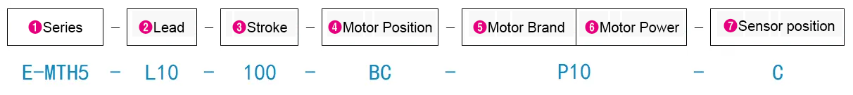
| Part Number |  Lead (mm) Lead (mm) |  Stroke Stroke(50m increments) |  Motor Position |  Motor Brand |  Motor Power | Sensor Position | Repetitive Positioning Accuracy (mm) | Max. Payload (kg) | Max. Speed (mm/sec) | Rated Thrust (N) | |
| Type | Horizontal Use | Vertical Use | |||||||||
| E-MTH5 | 5 | 50~800 | BC (Motor Direct Connection) BM (Motor On Lower Side) BL (Motor On Left Side) BR (Motor On Right Side) | M (Mitsubishi) P (Panasonic) Y (Yaskawa) T (Delta Electronics) Z (Prepared by Customer) | 10 (100W) | C (External Motor Side) D (External Motor Opposite Side) | ±0.01 | 10 | 3 | 250 | 341 |
| 10 | 5 | 1.5 | 500 | 170 | |||||||
A motor is not included to this product and it must be purchased separately.When the stroke exceeds 600mm, ball screw resonance will occur. In this case, reduce the movement speed.Select a motor with brake for vertical use.When Z is selected as the motor brand (prepared by customer), please provide the motor model and power when placing an order. (If necessary, provide the motor mounting dimensions)As the drawings are schematic diagrams, please confirm the detailed dimensions according to CAD data.
■Allowable Load Torque Table
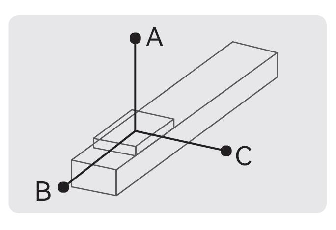
| Horizontal Installation | A | B | C | |
| Lead 5 | 5kg | 280 | 24 | 55 |
| 10kg | 120 | 10 | 22 | |
| Lead 10 | 3kg | 245 | 40 | 78 |
| 5kg | 140 | 22 | 43 | |
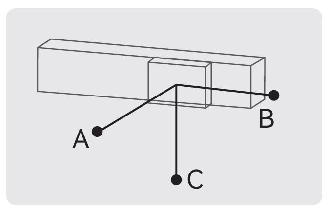
| Wall Installation | A | B | C | |
| Lead 5 | 5kg | 51 | 30 | 195 |
| 10kg | 20 | 15 | 231 | |
| Lead 10 | 3kg | 74 | 37 | 131 |
| 5kg | 40 | 20 | 131 | |
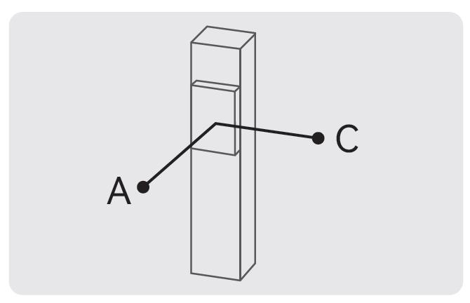
| Vertical Installation | A | C | |
| Lead 5 | 1kg | 140 | 140 |
| 3kg | 47 | 47 | |
| Lead 10 | 1kg | 125 | 125 |
| 1.5kg | 83 | 83 | |
310
■Static Allowable Load Inertia
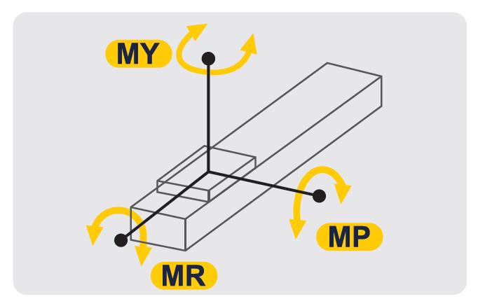
| Horizontal Installation | |
| MY | 16 |
| MP | 20 |
| MR | 19 |
The product has a service life of 10,000 kilometers under standard operating conditions.■List of Recommended Servo Motors
| Brand | Motor Code | With/Without Brake | Motor Power | Power Voltage | Servo Motor Model | Servo Drive Model |
| Mitsubishi | M | Without Brake (Horizontal Use) | 100W | 220V | HG-KR12 | MR-J4-10A |
| With Brake (Vertical Use) | HG-KR13B | |||||
| Panasonic | P | Without Brake (Horizontal Use) | 100W | 220V | MSMF012L1U2M | MADLN05SG |
| With Brake (Vertical Use) | MSMF012L1V2M | |||||
| Yaskawa | Y | Without Brake (Horizontal Use) | 100W | 220V | SGM7J01AFC6S | SGD7SR90A00A002 |
| With Brake (Vertical Use) | SGM7J01AFC6E | |||||
| Delta | T | Without Brake (Horizontal Use) | 100W | 220V | ECMA-C20401RS | ASD-B2-0121-B |
| With Brake (Vertical Use) | ECMA-C20401SS |
■Motor Mounting Port
■Avoid using single-axis drive products in the following environments
①Dusty environment (especially metal powder)
②Environment with splashing water and oil
③Near fire sources
④Environment with excessive organic solutions and salt
⑤Environment with direct sunlight and heat radiation
⑥Environment subject to strong vibration and shock
⑦Environment with corrosive gas, combustible gas
■Single-axis robot operating environment
Operating environment: normal temperature (no freezing, non-condensation)
| Effective Stroke | 50 | 100 | 150 | 200 | 250 | 300 | 350 | 400 | 450 | 500 | 550 | 600 | 650 | 700 | 750 | 800 |
| L | 216 | 266 | 316 | 366 | 416 | 466 | 516 | 566 | 616 | 666 | 716 | 766 | 816 | 866 | 916 | 966 |
| A | 60 | 30 | 40 | 50 | 60 | 30 | 40 | 50 | 60 | 30 | 40 | 50 | 60 | 30 | 40 | 50 |
| M | 2 | 4 | 5 | 6 | 7 | 9 | 10 | 11 | 12 | 14 | 15 | 16 | 17 | 19 | 20 | 21 |
| N | 3 | 5 | 6 | 7 | 8 | 10 | 11 | 12 | 13 | 15 | 16 | 17 | 18 | 20 | 21 | 22 |
| KG | 1.56 | 1.71 | 1.85 | 2 | 2.14 | 2.29 | 2.44 | 2.58 | 2.73 | 2.87 | 3.02 | 3.17 | 3.31 | 3.46 | 3.6 | 3.75 |
| Effective Stroke | 50 | 100 | 150 | 200 | 250 | 300 | 350 | 400 | 450 | 500 | 550 | 600 | 650 | 700 | 750 | 800 |
| L | 208 | 258 | 308 | 358 | 408 | 458 | 508 | 558 | 608 | 658 | 708 | 758 | 808 | 858 | 908 | 958 |
| A | 60 | 30 | 40 | 50 | 60 | 30 | 40 | 50 | 60 | 30 | 40 | 50 | 60 | 30 | 40 | 50 |
| M | 2 | 4 | 5 | 6 | 7 | 9 | 10 | 11 | 12 | 14 | 15 | 16 | 17 | 19 | 20 | 21 |
| N | 3 | 5 | 6 | 7 | 8 | 10 | 11 | 12 | 13 | 15 | 16 | 17 | 18 | 20 | 21 | 22 |
| KG | 1.66 | 1.81 | 1.95 | 2.1 | 2.24 | 2.39 | 2.54 | 2.68 | 2.83 | 2.97 | 3.12 | 3.27 | 3.41 | 3.56 | 3.7 | 3.85 |
| Part Number | Lead (mm) | Stroke (50m increments) | Motor Position | Motor Brand | Motor Power | Sensor Position | Repetitive Positioning Accuracy (mm) | Max. Payload (kg) | Max. Speed (mm/sec) | Rated Thrust (N) | |
| Type | Horizontal Use | Vertical Use | |||||||||
| E-MTH5 | 5 | 50~800 | BC (Motor Direct Connection) BM (Motor On Lower Side) BL (Motor On Left Side) BR (Motor On Right Side) | M (Mitsubishi) P (Panasonic) Y (Yaskawa) T (Delta Electronics) Z (Prepared by Customer) | 10 (100W) | C (External Motor Side) D (External Motor Opposite Side) | ±0.01 | 10 | 3 | 250 | 341 |
| 10 | 5 | 1.5 | 500 | 170 | |||||||
A motor is not included to this product and it must be purchased separately.When the stroke exceeds 600mm, ball screw resonance will occur. In this case, reduce the movement speed.Select a motor with brake for vertical use.When Z is selected as the motor brand (prepared by customer), please provide the motor model and power when placing an order. (If necessary, provide the motor mounting dimensions)As the drawings are schematic diagrams, please confirm the detailed dimensions according to CAD data.| Drive Method | Ball Screw | |
| Ball Screw | Accuracy grade | C7 |
| O.D. (mm) | Φ12 | |
| Body width (mm) | 51 | |
| High Rigidity Linear Guide (mm) | W24xH8.5 | |
| Drive Power (W) | 100 | |
| Operating Environment | General | |
| Part Number | Lead (mm) | Motor Power (W) | Max. Movement Speed (mm/sec) | |||||||||||||||
| 50 | 100 | 150 | 200 | 250 | 300 | 350 | 400 | 450 | 500 | 550 | 600 | 650 | 700 | 750 | 800 | |||
| E-MTH5 | 5 | 100 | 250 | 225 | 200 | 175 | 150 | |||||||||||
| 10 | 500 | 450 | 400 | 350 | 300 | |||||||||||||
Values in the table are reference values calculated according to the critical speed and DN value of the ball screw.Values in the table are maximum safety speeds available for each stroke. As ball screws may resonate at longer strokes, such conditions as abnormal sound and vibration may occur when operating at the maximum speed. Therefore, the moving speed should be reduced appropriately.| Components | Body | Embedded Guide | Screw | Nut | Slide Block | Cover |
| Material | Aluminum Alloy | Bearing Steel | Carbon Steel | Alloy Steel | Aluminum Alloy | Stainless Steel |
| Surface Treatment | Anodized | - | - | - | Anodized | - |
Part Number
CAD Data download and 3D preview are not available because the part number has not yet been determined.
- *In order to open the CAD Data download and 3D preview screen, the part number must be fixed.
- Please confirm the part number from "Specification / Dimension"on the left side, and then perform the CAD Data Download / 3D Preview operation.
| Part Number |
|---|
| E-MTH5-L5-[50-800/50]-[BC,BL,BM,BR]-M10-[C,D] |
| E-MTH5-L5-[50-800/50]-[BC,BL,BM,BR]-P10-[C,D] |
| E-MTH5-L5-[50-800/50]-[BC,BL,BM,BR]-T10-[C,D] |
| E-MTH5-L5-[50-800/50]-[BC,BL,BM,BR]-Y10-[C,D] |
| E-MTH5-L5-[50-800/50]-[BC,BL,BM,BR]-Z-[C,D] |
| E-MTH5-L10-[50-800/50]-[BC,BL,BM,BR]-M10-[C,D] |
| E-MTH5-L10-[50-800/50]-[BC,BL,BM,BR]-P10-[C,D] |
| E-MTH5-L10-[50-800/50]-[BC,BL,BM,BR]-T10-[C,D] |
| E-MTH5-L10-[50-800/50]-[BC,BL,BM,BR]-Y10-[C,D] |
| E-MTH5-L10-[50-800/50]-[BC,BL,BM,BR]-Z-[C,D] |
| Part Number | Standard Unit Price | Minimum order quantity | Volume Discount | Days to Ship | Lead | Effective Stroke (mm) | Motor Position | Motor Brand & Power | Sensor Position |
|---|---|---|---|---|---|---|---|---|---|
- | 1 Piece(s) | 11 Day(s) | 5 | 50 ~ 800 | BC Motor Direct Connection / BL Motor On Left Side / BM Motor On Lower Side / BR Motor On Right Side | M10 Mitsubishi 100W | C Motor Side / D Motor Opposite Side | ||
- | 1 Piece(s) | 11 Day(s) | 5 | 50 ~ 800 | BC Motor Direct Connection / BL Motor On Left Side / BM Motor On Lower Side / BR Motor On Right Side | P10 Panasonic 100W | C Motor Side / D Motor Opposite Side | ||
- | 1 Piece(s) | 11 Day(s) | 5 | 50 ~ 800 | BC Motor Direct Connection / BL Motor On Left Side / BM Motor On Lower Side / BR Motor On Right Side | T10 Delta 100W | C Motor Side / D Motor Opposite Side | ||
- | 1 Piece(s) | 11 Day(s) | 5 | 50 ~ 800 | BC Motor Direct Connection / BL Motor On Left Side / BM Motor On Lower Side / BR Motor On Right Side | Y10 Yaskawa 100W | C Motor Side / D Motor Opposite Side | ||
- | 1 Piece(s) | 11 Day(s) | 5 | 50 ~ 800 | BC Motor Direct Connection / BL Motor On Left Side / BM Motor On Lower Side / BR Motor On Right Side | Z Prepared by Customer | C Motor Side / D Motor Opposite Side | ||
- | 1 Piece(s) | 11 Day(s) | 10 | 50 ~ 800 | BC Motor Direct Connection / BL Motor On Left Side / BM Motor On Lower Side / BR Motor On Right Side | M10 Mitsubishi 100W | C Motor Side / D Motor Opposite Side | ||
- | 1 Piece(s) | 11 Day(s) | 10 | 50 ~ 800 | BC Motor Direct Connection / BL Motor On Left Side / BM Motor On Lower Side / BR Motor On Right Side | P10 Panasonic 100W | C Motor Side / D Motor Opposite Side | ||
- | 1 Piece(s) | 11 Day(s) | 10 | 50 ~ 800 | BC Motor Direct Connection / BL Motor On Left Side / BM Motor On Lower Side / BR Motor On Right Side | T10 Delta 100W | C Motor Side / D Motor Opposite Side | ||
- | 1 Piece(s) | 11 Day(s) | 10 | 50 ~ 800 | BC Motor Direct Connection / BL Motor On Left Side / BM Motor On Lower Side / BR Motor On Right Side | Y10 Yaskawa 100W | C Motor Side / D Motor Opposite Side | ||
- | 1 Piece(s) | 11 Day(s) | 10 | 50 ~ 800 | BC Motor Direct Connection / BL Motor On Left Side / BM Motor On Lower Side / BR Motor On Right Side | Z Prepared by Customer | C Motor Side / D Motor Opposite Side |
Loading...
Basic Information
| Type | Slider | Drive Method | Rolled Ball Screw | Main Body, Peripheral Components | Main Body |
|---|---|---|---|---|---|
| Positioning Repeatability(µm) | ±10 | Cable | Not Provided | Number of Tables | 1 pc. |
Specification/Dimensions
-
Lead
-
Effective Stroke(mm)
-
Motor Position
- BC Motor Direct Connection
- BL Motor On Left Side
- BM Motor On Lower Side
- BR Motor On Right Side
-
Motor Brand & Power
-
Sensor Position
- C Motor Side
- D Motor Opposite Side
-
type
- E-MTH5
-
CAD
- 2D
- 3D
Days to Ship
-
- All
- 11 Day(s) or Less
Specify Alterations
- The specifications and dimensions of some parts may not be fully covered. For exact details, refer to manufacturer catalogs .
Frequently asked question (FAQ)
- Question: Is the sensor shipped after installation?
- Answer: The sensor components are shipped together with the main unit and need to be installed by the customer upon arrival.
- Question: Do actuators require regular maintenance?
- Answer: Maintenance is required. Grease dry-out will cause the product to rust, and dry friction between the guide slider and the steel balls at high speeds will cause wear and tear, significantly reducing product life.
- Question: Does the E-MTH series come with a motor?
- Answer: No it doesn’t. Customers need to use the motor brand they trust, depending on the actual conditions. Be sure to ensure concentricity when mounting the motor, as a skewed motor shaft and screw will affect use.
Tech Support
Payment Method
- Credit Card
- PayPal
- Bank Transfer
Social Media
MISUMI Contact
Copyright © MISUMI Corporation All Rights Reserved.
How can we improve?
How can we improve?