(!)Due to Microsoft's end of support for Internet Explorer 11 on 15/06/2022, this site does not support the recommended environment.
Instead, please kindly use other browsers like Google Chrome, Microsoft Edge or Mozilla Firefox.
50,000 Stock items for Same Day Ship Out.
All Categories
Categories
- Automation Components
A wide variety of standard and configurable components for factory automation engineers in industries such as automotive, semiconductor, packaging, medical and many more.
- Linear Motion
- Rotary Motion
- Connecting Parts
- Rotary Power Transmission
- Motors
- Conveyors & Material Handling
- Locating, Positioning, Jigs & Fixtures
- Inspection
- Sensors, Switches
- Pneumatics, Hydraulics
- Vacuum Components
- Hydraulic Equipment
- Discharging / Painting Devices
- Pipe, Tubes, Hoses & Fittings
- Modules, Units
- Heaters, Temperature Control
- Framing & Support
- Casters, Leveling Mounts, Posts
- Doors, Cabinet Hardware
- Springs, Shock Absorbers
- Adjusting, Fastening, Magnets
- Antivibration, Soundproofing Materials, Safety Products
- Fasteners
A good selection of accessories such as screws, bolts, washers and nuts that you may need for your daily engineering usage.
- Materials
Browse industrial materials ranging from heat insulating plates, sponges, to metal and plastic materials in different sizes to meet your various applications.
- Wiring Components
A wide variety of wiring parts for connecting and protecting control and PC parts including Connectors, Cables, Electric Wires, Crimping Terminals and more.
- LAN Cables / Industrial Network Cables
- Cables by Application
- Cables with Connectors
- RS232 / Personal Computers / AV Cables
- Wires/Cables
- Connectors (General Purpose)
- Crimp Terminals
- Zip Ties
- Cable Glands
- Cable Bushings/Clips/Stickers
- Screws/Spacers
- Cable Accessories
- Tubes
- Protection Tubes
- Ducts/Wiremolds
- General Purpose Tools
- Dedicated Tools
- Soldering Supplies
- Electrical & Controls
A wide variety of controls and PC parts for electrical engineers including Controls, Powers, PC parts and more.
- Cutting Tools
A wide variety of cutting tools for many uses and work materials including End Mills, Drills, Cutters, Reamers, Turning Tools and more.
- Carbide End Mills
- HSS End Mills
- Milling Cutter Inserts/Holders
- Customized Straight Blade End Mills
- Dedicated Cutters
- Turning Tools
- Drill Bits
- Screw-Hole-Related Tools
- Reamers
- Chamfering / Centering Tools
- Fixtures Related to Cutting Tools
- Step Drills
- Hole Saws
- Clean Key Cutters
- Core Drills (Tip Tools)
- Magnetic Drilling Machine Cutters
- Drill Bits for Electric Drilling Machines
- Woodworking Drill Cutters
- Drills for Concrete
- Processing Tools
A wide variety of tools and supplies used in processing including Machine Tools, Measurement Tools, Grinding and Polishing Supplies and more.
- Material Handling & Storage
A wide variety of goods used in shipment, material handling and warehouse including Tape supplies, Stretch film, Truck, Shelf, Crane and more.
- Tape Supplies
- Cushioning Materials
- Stretch Films
- Cardboard
- Plastic Bags
- PP Bands
- Magic Tapes / Tying Belts
- Rubber Bands
- Strings/Ropes
- Cable Ties
- Tags
- Labelers
- Unpacking Cutters
- Packing Support Equipment
- Cloth Sheets for Packing
- Conveyance/Dolly Carts
- Tool Wagons
- Tool Cabinets / Container Racks
- Lifters / Hand Pallets
- Container Pallets
- Storage Supplies
- Shelves/Racks
- Work Benches
- Suspended Clamps/Suspended Belts
- Jack Winches
- Chain Block Cranes
- Bottles/Containers
- Bicycle Storage Area
- Safety & General Supplies
A large variety of goods for every kind of factories and offices including Protection items, Cleaning supplies, sanitations, office supplies and more.
- Lab & Clean Room Supplies
A large variety of items used in R&D and Clean Room including research Equipment, Laboratory Essentials, Analysis Supplies, Clean Environment-Related Equipment and more.
- Press Die Components
Choose from thousands of standard stamping die components including Punch & Die, Gas Springs, Guide Components, Coil Springs and many more.
- Plastic Mold Components
Browse our wide variety of mold components including Ejector Pins, Sleeves, Leader Components, Sprue Bushings and many more.
- Ejector Pins
- Sleeves, Center Pins
- Core Pins
- Sprue bushings, Gates, and other components
- Date Mark Inserts, Recycle Mark Inserts, Pins with Gas Vent
- Undercut, Plates
- Leader Components, Components for Ejector Space
- Mold Opening Controllers
- Cooling or Heating Components
- Accessories, Others
- Components of Large Mold, Die Casting
- Injection Molding Components
Browse our injection molding components including Heating Items, Couplers, Hoses and more.
- Injection Molding Machine Products
- Accessories of Equipment
- Auxiliary Equipment
- Air Nippers
- Air Cylinders
- Air Chuck for Runner
- Chuck Board Components
- Frames
- Suction Components
- Parallel Air Chuck
- Special Air Chuck
- Chemical for Injection Molding
- Mold Maintenance
- Heating Items
- Heat Insulation Sheets
- Couplers, Plugs, One-touch Joints
- Tubes, Hoses, Peripheral Components
Search by Application
Brands


- Please be informed that our office is closed during the upcoming Labour Day Holiday in 2024. We would also like to inform you that there may be a potential delay in response/shipment from the supplier due to the Japan Golden Week holiday which falls from 29th April to 6th May 2024. Click here for details.
- Please Note our New Address (effective April 1, 2024): 331 North Bridge Rd, #05-01 Odeon 331, Singapore 188720.
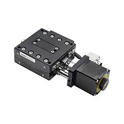
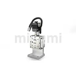
1-Axis Motorized Goniometer Stages Ball Screw Type


- Volume Discount
Part Number
Configured Part Number is shown.
Feature 2: Optimized structure and low prices are achieved through local production.
Feature 3: Quick disassembling is achieved by adding dowel holes to the stage surface.
Feature 4: Standard equipped driver is applicable to dual pulse and pulse + direction control, which can be used under multiple working conditions.
 Material Aluminum Alloy
 Surface Treatment Black Anodized
| Part Number |  Sensor SensorPosition |  Driver Driver |  Cable Cable | Mechanical Specification | Accuracy Specification | Sensor | ||||||||
 Type Type |  No. No. | Stage Surface (mm) | Travel Distance (°) | Load Capacity (N) | Height of Rotation Center (mm) | Weight (kg) | Maximum Speed (°/sec) | One-Way Positioning Accuracy | Repetitive Positioning Accuracy | Limit Sensor | Origin Sensor (ORG1) | |||
| E-GMPG | 60-50 | A | 60×60 | ±9 | 49 | 50±0.2 | 0.5 | 10.5 | Within 0.08° | Within ±0.01° | Provided | Provided | ||
| 60-75 | L (forward) | 2 (2m cable) | ±5.5 | 75±0.2 | 7 | |||||||||
| 60-100 | R (reverse) | 4 (4m cable) | ±5 | 100±0.2 | 5.5 | |||||||||
| 60-125 | ±4 | 125±0.2 | 4.5 | |||||||||||
■ Universal Specifications
| No. | 60-50 | 60-75 | 60-100 | 60-125 | |
| Feed Screw | Ball Screw Φ6, Lead 1mm | ||||
| Guide | Curved cross roller guide | ||||
| Motor | Type | 2-Phase Stepper Motor 1.3A/Phase | |||
| Step Angle | 1.8° | ||||
| Resolution (Pulse) Full | ≒0.0052° | ≒0.0036° | ≒0.0027° | ≒0.0022° | |
| Driver | Power Voltage | DC12~50V | |||
| Output Current | 0.1~2.2A | ||||
| Pulse Signal Voltage | 5~24V | ||||
| Subdivision | 200~51200 | ||||
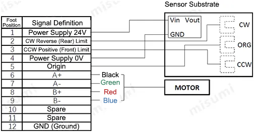
| Connector | Part Number | HR10A-10R-12P (HIROSE) | |||
| Receiving Side Part Number | HR10A-10P-12S (HIROSE) | ||||
| Sensor Substrate | Limit Sensor | Provided | |||
| Origin Sensor | Provided | ||||
| Power Voltage | DC24V±10% | ||||
| Sensor Type | Photomicro Sensor EE-SX4320 (OMRON) | ||||
| Control Output | NPN Open Collector Output | ||||
| Output Logic | When detecting (shading): output transistor OFF (non-conductive) | ||||
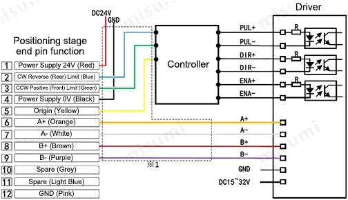
* 1. The cable in the dotted box is 2m or 4m cable
The applicable driver supports dual pulse and pulse + direction control. For the mounting dimensions and 3D download, reference can be made to C-DR42A
. Compared with C-DR42A, the applicable driver has the same external dimensions, but comes with an additional dual-pulse control function.
Operating environment: 10~50℃, 20~70% RH (without condensation)
Recommended operating environment: 22±5℃, 20~70%RH (without condensation)
Please avoid using this positioning stage in the following environments
① Dusty environment (especially metal powder)
② Environment with direct sunlight and thermal radiation
③ Environment near fire sources
④ Environment containing corrosive gases and flammable gases
⑤ Environment with splashing water and oil
⑥ Environment with strong vibration and impact⑦ Environment containing organic solutions and salt
■Positioning stage maintenance
A uniform maintenance standard is not available, and the maintenance method is subject to the type of grease and operating environment. Based on the driving conditions and guide types, make sure to check the grease once a month.
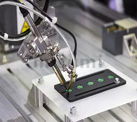
| Electronics/Home Appliance | Automotive | Medical | ||
 |  |  | ||
| Smart Phones | Semiconductor | Lithium battery | ||
 |  | 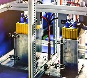 |
| Economy series X-Axis Motorized Positioning Stages | Economy series XY-Axis Motorized Positioning Stages | Economy series Z-Axis Motorized Positioning Stages |
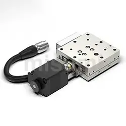 | 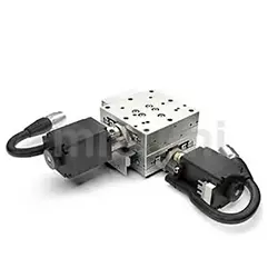 |  |
| Representative model: C-XMBS420-L-A-2 | Representative model: C-XYMBS420-L-A-2 | Representative model: C-ZMBS420-L-A-2 |
Part Number
CAD Data download and 3D preview are not available because the part number has not yet been determined.
- *In order to open the CAD Data download and 3D preview screen, the part number must be fixed.
- Please confirm the part number from "Specification / Dimension"on the left side, and then perform the CAD Data Download / 3D Preview operation.
| Part Number | Standard Unit Price | Minimum order quantity | Volume Discount | Days to Ship | Minimum Resolution (Angle) (deg) | Part Number | Sensor Cover Position | Cable |
|---|---|---|---|---|---|---|---|---|
SGD 1,236.40 | 1 Piece(s) | Available | 8 Day(s) | 0.0052 | E-GMPG60-50 | L | 2 | |
SGD 1,255.70 | 1 Piece(s) | Available | 8 Day(s) | 0.0052 | E-GMPG60-50 | L | 4 | |
SGD 1,236.40 | 1 Piece(s) | Available | 8 Day(s) | 0.0052 | E-GMPG60-50 | R | 2 | |
SGD 1,255.70 | 1 Piece(s) | Available | 8 Day(s) | 0.0052 | E-GMPG60-50 | R | 4 | |
SGD 1,236.40 | 1 Piece(s) | Available | 8 Day(s) | 0.0036 | E-GMPG60-75 | L | 2 | |
SGD 1,255.70 | 1 Piece(s) | Available | 8 Day(s) | 0.0036 | E-GMPG60-75 | L | 4 | |
SGD 1,236.40 | 1 Piece(s) | Available | 8 Day(s) | 0.0036 | E-GMPG60-75 | R | 2 | |
SGD 1,255.70 | 1 Piece(s) | Available | 8 Day(s) | 0.0036 | E-GMPG60-75 | R | 4 | |
SGD 1,236.40 | 1 Piece(s) | Available | 8 Day(s) | 0.0027 | E-GMPG60-100 | L | 2 | |
SGD 1,255.70 | 1 Piece(s) | Available | 8 Day(s) | 0.0027 | E-GMPG60-100 | L | 4 | |
SGD 1,236.40 | 1 Piece(s) | Available | 8 Day(s) | 0.0027 | E-GMPG60-100 | R | 2 | |
SGD 1,255.70 | 1 Piece(s) | Available | 8 Day(s) | 0.0027 | E-GMPG60-100 | R | 4 | |
SGD 1,236.40 | 1 Piece(s) | Available | 8 Day(s) | 0.0027 | E-GMPG60-125 | L | 2 | |
SGD 1,255.70 | 1 Piece(s) | Available | 8 Day(s) | 0.0022 | E-GMPG60-125 | L | 4 | |
SGD 1,236.40 | 1 Piece(s) | Available | 8 Day(s) | 0.0022 | E-GMPG60-125 | R | 2 | |
SGD 1,255.70 | 1 Piece(s) | Available | 8 Day(s) | 0.0022 | E-GMPG60-125 | R | 4 |
Loading...
Material Aluminum Alloy Surface Treatment Black Anodized| Part Number | Sensor Position | Driver | Cable | Mechanical Specification | Accuracy Specification | Sensor | ||||||||
| Type | No. | Stage Surface (mm) | Travel Distance (°) | Load Capacity (N) | Height of Rotation Center (mm) | Weight (kg) | Maximum Speed (°/sec) | One-Way Positioning Accuracy | Repetitive Positioning Accuracy | Limit Sensor | Origin Sensor (ORG1) | |||
| E-GMPG | 60-50 | A | 60×60 | ±9 | 49 | 50±0.2 | 0.5 | 10.5 | Within 0.08° | Within ±0.01° | Provided | Provided | ||
| 60-75 | L (forward) | 2 (2m cable) | ±5.5 | 75±0.2 | 7 | |||||||||
| 60-100 | R (reverse) | 4 (4m cable) | ±5 | 100±0.2 | 5.5 | |||||||||
| 60-125 | ±4 | 125±0.2 | 4.5 | |||||||||||
■ Universal Specifications
| No. | 60-50 | 60-75 | 60-100 | 60-125 | |
| Feed Screw | Ball Screw Φ6, Lead 1mm | ||||
| Guide | Curved cross roller guide | ||||
| Motor | Type | 2-Phase Stepper Motor 1.3A/Phase | |||
| Step Angle | 1.8° | ||||
| Resolution (Pulse) Full | ≒0.0052° | ≒0.0036° | ≒0.0027° | ≒0.0022° | |
| Driver | Power Voltage | DC12~50V | |||
| Output Current | 0.1~2.2A | ||||
| Pulse Signal Voltage | 5~24V | ||||
| Subdivision | 200~51200 | ||||
| Connector | Part Number | HR10A-10R-12P (HIROSE) | |||
| Receiving Side Part Number | HR10A-10P-12S (HIROSE) | ||||
| Sensor Substrate | Limit Sensor | Provided | |||
| Origin Sensor | Provided | ||||
| Power Voltage | DC24V±10% | ||||
| Sensor Type | Photomicro Sensor EE-SX4320 (OMRON) | ||||
| Control Output | NPN Open Collector Output | ||||
| Output Logic | When detecting (shading): output transistor OFF (non-conductive) | ||||
.jpg)
■Timing Diagram
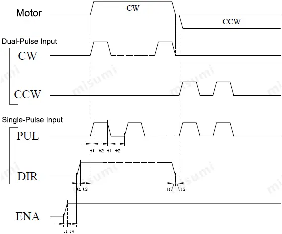
t1<0.1 us t2≥0.9 us t3≥10 us
t4: ENA (Enable Signal) t4 should be at least 10 μs ahead of DIR, and it is determined as high. Generally, ENA+ and ENA- are recommended to be suspended.
Basic Information
| Type | Goniometer Stage | Table Length(mm) | 60 | Table Feeding Method | Ball Screw |
|---|---|---|---|---|---|
| Table Width(mm) | 60 | Load Capacity (Range)(N) | 30.1~50 | Motor, Motor Characteristics | 2-Phase Stepping Motor - Standard |
| Material | Aluminum(Aluminum Alloy) | Guide | Cross Roller | Surface Treatment | Black Anodize |
| Through Hole (Table Center Hole) | Not Provided | Load Capacity(N) | 49 | Driver | B |
Specification/Dimensions
-
Minimum Resolution (Angle)(deg)
-
Part Number
- E-GMPG60-125
- E-GMPG60-100
- E-GMPG60-75
- E-GMPG60-50
-
Sensor Cover Position
- L
- R
-
Cable
- 2
- 4
-
type
- E-GMPG
-
CAD
- 2D
- 3D
Days to Ship
-
- All
- 8 Day(s) or Less
Specify Alterations
- The specifications and dimensions of some parts may not be fully covered. For exact details, refer to manufacturer catalogs .
Tech Support
Payment Method
- Credit Card
- PayPal
- Bank Transfer
Social Media
MISUMI Contact
Copyright © MISUMI Corporation All Rights Reserved.
How can we improve?
How can we improve?