(!)Due to Microsoft's end of support for Internet Explorer 11 on 15/06/2022, this site does not support the recommended environment.
Instead, please kindly use other browsers like Google Chrome, Microsoft Edge or Mozilla Firefox.
50,000 Stock items for Same Day Ship Out.
All Categories
Categories
- Automation Components
A wide variety of standard and configurable components for factory automation engineers in industries such as automotive, semiconductor, packaging, medical and many more.
- Linear Motion
- Rotary Motion
- Connecting Parts
- Rotary Power Transmission
- Motors
- Conveyors & Material Handling
- Locating, Positioning, Jigs & Fixtures
- Inspection
- Sensors, Switches
- Pneumatics, Hydraulics
- Vacuum Components
- Hydraulic Equipment
- Discharging / Painting Devices
- Pipe, Tubes, Hoses & Fittings
- Modules, Units
- Heaters, Temperature Control
- Framing & Support
- Casters, Leveling Mounts, Posts
- Doors, Cabinet Hardware
- Springs, Shock Absorbers
- Adjusting, Fastening, Magnets
- Antivibration, Soundproofing Materials, Safety Products
- Fasteners
A good selection of accessories such as screws, bolts, washers and nuts that you may need for your daily engineering usage.
- Materials
Browse industrial materials ranging from heat insulating plates, sponges, to metal and plastic materials in different sizes to meet your various applications.
- Wiring Components
A wide variety of wiring parts for connecting and protecting control and PC parts including Connectors, Cables, Electric Wires, Crimping Terminals and more.
- LAN Cables / Industrial Network Cables
- Cables by Application
- Cables with Connectors
- RS232 / Personal Computers / AV Cables
- Wires/Cables
- Connectors (General Purpose)
- Crimp Terminals
- Zip Ties
- Cable Glands
- Cable Bushings/Clips/Stickers
- Screws/Spacers
- Cable Accessories
- Tubes
- Protection Tubes
- Ducts/Wiremolds
- General Purpose Tools
- Dedicated Tools
- Soldering Supplies
- Electrical & Controls
A wide variety of controls and PC parts for electrical engineers including Controls, Powers, PC parts and more.
- Cutting Tools
A wide variety of cutting tools for many uses and work materials including End Mills, Drills, Cutters, Reamers, Turning Tools and more.
- Carbide End Mills
- HSS End Mills
- Milling Cutter Inserts/Holders
- Customized Straight Blade End Mills
- Dedicated Cutters
- Turning Tools
- Drill Bits
- Screw-Hole-Related Tools
- Reamers
- Chamfering / Centering Tools
- Fixtures Related to Cutting Tools
- Step Drills
- Hole Saws
- Clean Key Cutters
- Core Drills (Tip Tools)
- Magnetic Drilling Machine Cutters
- Drill Bits for Electric Drilling Machines
- Woodworking Drill Cutters
- Drills for Concrete
- Processing Tools
A wide variety of tools and supplies used in processing including Machine Tools, Measurement Tools, Grinding and Polishing Supplies and more.
- Material Handling & Storage
A wide variety of goods used in shipment, material handling and warehouse including Tape supplies, Stretch film, Truck, Shelf, Crane and more.
- Tape Supplies
- Cushioning Materials
- Stretch Films
- Cardboard
- Plastic Bags
- PP Bands
- Magic Tapes / Tying Belts
- Rubber Bands
- Strings/Ropes
- Cable Ties
- Tags
- Labelers
- Unpacking Cutters
- Packing Support Equipment
- Cloth Sheets for Packing
- Conveyance/Dolly Carts
- Tool Wagons
- Tool Cabinets / Container Racks
- Lifters / Hand Pallets
- Container Pallets
- Storage Supplies
- Shelves/Racks
- Work Benches
- Suspended Clamps/Suspended Belts
- Jack Winches
- Chain Block Cranes
- Bottles/Containers
- Bicycle Storage Area
- Safety & General Supplies
A large variety of goods for every kind of factories and offices including Protection items, Cleaning supplies, sanitations, office supplies and more.
- Lab & Clean Room Supplies
A large variety of items used in R&D and Clean Room including research Equipment, Laboratory Essentials, Analysis Supplies, Clean Environment-Related Equipment and more.
- Press Die Components
Choose from thousands of standard stamping die components including Punch & Die, Gas Springs, Guide Components, Coil Springs and many more.
- Plastic Mold Components
Browse our wide variety of mold components including Ejector Pins, Sleeves, Leader Components, Sprue Bushings and many more.
- Ejector Pins
- Sleeves, Center Pins
- Core Pins
- Sprue bushings, Gates, and other components
- Date Mark Inserts, Recycle Mark Inserts, Pins with Gas Vent
- Undercut, Plates
- Leader Components, Components for Ejector Space
- Mold Opening Controllers
- Cooling or Heating Components
- Accessories, Others
- Components of Large Mold, Die Casting
- Injection Molding Components
Browse our injection molding components including Heating Items, Couplers, Hoses and more.
- Injection Molding Machine Products
- Accessories of Equipment
- Auxiliary Equipment
- Air Nippers
- Air Cylinders
- Air Chuck for Runner
- Chuck Board Components
- Frames
- Suction Components
- Parallel Air Chuck
- Special Air Chuck
- Chemical for Injection Molding
- Mold Maintenance
- Heating Items
- Heat Insulation Sheets
- Couplers, Plugs, One-touch Joints
- Tubes, Hoses, Peripheral Components
Search by Application
Brands


- Please be informed that our office is closed during the upcoming Labour Day Holiday in 2024. We would also like to inform you that there may be a potential delay in response/shipment from the supplier due to the Japan Golden Week holiday which falls from 29th April to 6th May 2024. Click here for details.
- Please Note our New Address (effective April 1, 2024): 331 North Bridge Rd, #05-01 Odeon 331, Singapore 188720.
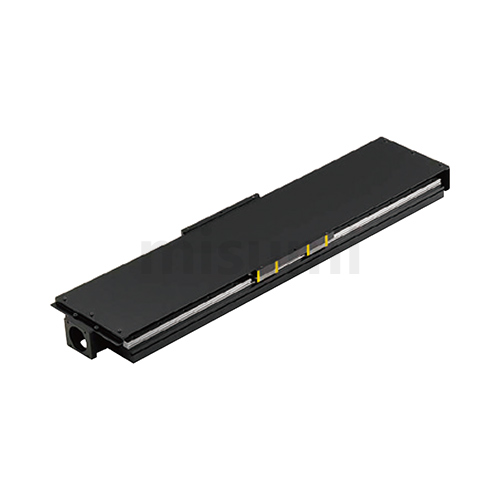
Single Axis Units Rolled Ball Screw With Cover
Part Number
Configured Part Number is shown.
by using a linear guide for medium and heavy load.
A single axis unit with cover can prevent damage to the single axis unit caused by dropping small parts, etc., and prevent liquids such as adhesive or grease from dripping inside the single axis unit. Safe use is ensured,
significantly reducing magement costs.
Feature 2: Low cost. Saves time in design, procurement and assembly. Significantly reduces labor costs for customers.
Feature 3: Heavy load resistance. Suitable for high and heavy load transfer thanks to the use of a linear guide for medium and heavy load.
Driven by rolled screw, two products (without cover type and with cover type) are added to the lineup.
 Accessories Accessories |  Material Material |  Surface Treatment Surface Treatment | Quantity | Note |
| Hexagon socket head bolt M5×10 | Iron | Trivalent Chromate Treatment (Black) | 4 | For fixing bracket |
| Part | Base | Table | Motor Bracket | Nut Bracket | Fixed Side Screw Support Unit | Support Side Bearing Housing | Stopper |
| Material | Aluminum Alloy | Aluminum Alloy | Aluminum Alloy | Aluminum Alloy | Iron | Aluminum Alloy | Resin |
| Surface Treatment | Black Anodized | Black Anodized | Black Anodized | Black Anodized | Ferroferric Oxide Protective Film | Black Anodized | - |

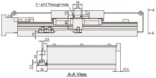
| Part Number | Selection | Rolled Ball Screw | W Workbench Width | H Total Height | H1 Guide Height | H2 Axis Height | Table | |||||||
 Type Type |  No. No. |  L LBase Length |  L1 L1Table Length | Diameter | Lead | W | t2 | M1 | P1 | P2 | ||||
| E-KUAC | 1510L 1520L | 340 | 150 | 15 | 10 20 | 220 | 74 | 28 | 32 | 220 | 22 | M5 | 120 | 195 |
| 400 | ||||||||||||||
| 460 | ||||||||||||||
| 520 | ||||||||||||||
| 580 | ||||||||||||||
| 2010L 2020L | 20 | 89 | 39 | 40 | ||||||||||
| 640 | ||||||||||||||
| 700 | ||||||||||||||
| 78 | 28 | 34 | ||||||||||||
| 760 | ||||||||||||||
| 820 | ||||||||||||||
| Part Number | Base | Base Mounting Hole | Motor Mounting Related Dimensions | |||||||||||||||||||||||||||||||||||||||||||||||||||||||||
| Type | No. | W1 | H4 | t1 | h1 | P3 | h | Q | S | P.C.D | D | D1 | H3 | N | N1 | N2 | N3 | d | M2 | R | ||||||||||||||||||||||||||||||||||||||||
| E-KUAC | 1510L 1520L | 208 | 49 | 12 | 20 | 120 | 11.5 |
|
| 70 | 50 | 45 | 62 | 45 | 5 | 40 | 15 | 10 | M5 | 10 | ||||||||||||||||||||||||||||||||||||||||
| 2010L | 61 | 29 | 70 | 57.5 | 39.5 | 20 | 12 | |||||||||||||||||||||||||||||||||||||||||||||||||||||
| 2020L | 55 | 20 | 64 | |||||||||||||||||||||||||||||||||||||||||||||||||||||||||
■Applicable Servo Motor Table
| Manufacturers | Part Number | Output Power (W) | Square Flange |
| Yaskawa Electric | SGM7J-02 | 200 | □60 |
| SGM7J-04 | 400 | ||
| Mitsubishi Electric | HG-MR23 | 200 | |
| HG-KR23 | 200 | ||
| HF-MP23 | 200 | ||
| HF-KP23 | 200 | ||
| HG-MR43 | 400 | ||
| HG-KR43 | 400 | ||
| HF-MP43 | 400 | ||
| HF-KP43 | 400 |
■Precision·Allowable Static Load
| Part Number | *Positioning Repeatability (mm) | Allowable Static Load (kg) | *Parallelism (mm) | ||||||||||||||||||||||
| Type | No. | Horizontal | Vertical | ||||||||||||||||||||||
| Rolled Ball Screw E-KUAC | 1510L | ±0.05 | 2897 | 153 |
| ||||||||||||||||||||
| 1520L | |||||||||||||||||||||||||
| 2010L | 4345 | 169 | |||||||||||||||||||||||
| 2020L | |||||||||||||||||||||||||

Ball Screw Coupling Side Shaft End Alterations
| Alterations | Code | Spec. | |||||||
| Machining fixed side shaft end keyways | KC | Adds keyways. KC= 1mm increments Ordering Code KC10 |
| ||||||
 | |||||||||
| Machining fixed side shaft end keyways | KLC | The machining position of keyways can be specified. K, S= 1mm increments Ordering Code KLC-K5-S2 |
| ||||||
 | |||||||||
| Machining fixed side shaft end plane | SC | Adds planes. SC= 1mm increments Ordering Code SC7 |
| ||||||
 | |||||||||
| Machining a plane at fixed side shaft end (2 places) | SWC | Adds planes at 2 places (90° position). SWC= 1mm increments Ordering Code SWC7 |
| ||||||
 | |||||||||
| Applicable Part Number | Code |
| E-KUAC 1510L/1520L | CW1 CW2 CW3 |
| E-KUAC 2010L/2020L |
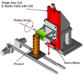
Model: E-KUAC1505-340-150
Description: Movement of deburring brush. Especially suitable for working conditions with variable lifting speed and durability requirements.
Application: A sufficiently rigid device is required to prevent vibration.
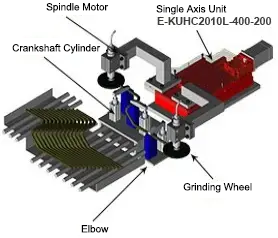
Model: E-KUHC2010L-400-200
Description: Movement and positioning for bending and grinding equipment of crankshafts.
Application: The part of the device that deviates from the base plate.

Model: E-KUAC2010L-580-200
Description: Movement and positioning of the sliding part during equidistant welding operations of section steel spot welding machines.
Application: A sufficiently rigid device is required to prevent clamping.


Mount by positioning on the side of the base.
 To ensure the precision of the single axis unit, fix it to an iron plate with flatness of ±0.02mm or less and
thickness of 20mm or more through the mounting holes of the base, otherwise the base will be deformed and jamming will occur.
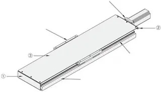
①Accessory Installation Diagram
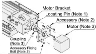
Note 2) Accessory and 4 M3x10 fixing bolts are included.
Note 3) Motor and coupling are not included.
②Cover Installation Procedure
Step 1: Fix the KU□C body on the device or workbench used by the customer.
Step 2: Install the attached brackets ①② onto the body.
Step 3: Fix the attached cover ③ onto the attached brackets ①② already installed in Step 2.
■Maintenance Method
①Grease Replenishment Method
After applying grease directly to the ball screw, slide the workbench over the full stroke to achieve overall uniform application.
Insert the grease gun into the nozzle on the linear guide and inject grease.
After injection, move the table over the full stroke several times to achieve overall uniform application.
Grease: Showa Shell Albania Grease S2.②Frequency of Grease Replenishment
Replenish grease every 6 months (or when the travel distance reaches 1000KM).
The replenishment interval varies with operating conditions and operating environment. Please make appropriate judgments.①The sensor unit, cover and the single axis unit are shipped in the same package. The customer installs by himself.
②Due to the large number of fine parts, please check the supplied parts immediately after unpacking.
③Turn on the power and use the product after ensuring safety in the surroundings, thus avoiding equipment damage or personal injury accidents.
■Operating Environment
Use at an ambient temperature of 50°C or less. Recommended operating temperature: 0 to 50℃ (without freezing or condensation).
■Avoid using the single axis unit in the following environments
| Linear Guides for Heavy Load | Single Axis Actuator LXH45 | Single Axis Actuator LX30 | ||
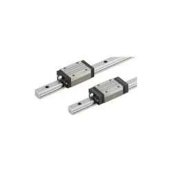 | 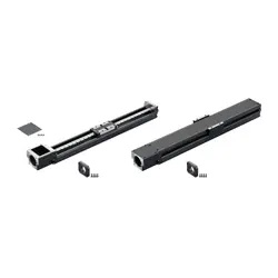 | 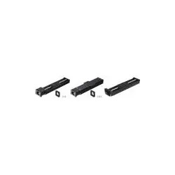 | ||
| Representative model: SX2R24-640 | Representative model: LXH4520-B1-N-640 | Representative model: LX3010-B1-N-600 |
Part Number
CAD Data download and 3D preview are not available because the part number has not yet been determined.
- *In order to open the CAD Data download and 3D preview screen, the part number must be fixed.
- Please confirm the part number from "Specification / Dimension"on the left side, and then perform the CAD Data Download / 3D Preview operation.
| Part Number |
|---|
| E-KUAC1510L-[340,400,460,520,580,640,700,760,820]-150 |
| E-KUAC1520L-[460,520,580,640,700,760,820]-150 |
| E-KUAC2010L-[400,460,520,580,640,700,760,820]-150 |
| E-KUAC2020L-[460,520,580,640,700,760,820]-150 |
| Part Number | Standard Unit Price | Minimum order quantity | Volume Discount | Days to Ship | Ball Screw Dia. (φ) | Ball Screw Lead (mm) | Overall Base Length [L] (mm) | Overall Base Length [L]Overall Base Length [L] (mm) |
|---|---|---|---|---|---|---|---|---|
- | 1 Piece(s) | 29 Day(s) | 15 | 10 | 340 ~ 820 | - | ||
- | 1 Piece(s) | 29 Day(s) | 15 | 20 | 460 ~ 820 | - | ||
- | 1 Piece(s) | 29 Day(s) | 20 | 10 | 760 ~ 820 | 400 ~ 700 | ||
- | 1 Piece(s) | 29 Day(s) | 20 | 20 | 460 ~ 820 | - |
Loading...
| Accessories | Material | Surface Treatment | Quantity | Note |
| Hexagon socket head bolt M5×10 | Iron | Trivalent Chromate Treatment (Black) | 4 | For fixing bracket |
| Part | Base | Table | Motor bracket | Nut Bracket | Fixed Side Screw Support Unit | Support Side Bearing Housing | Stopper |
| Material | Aluminum Alloy | Aluminum Alloy | Aluminum Alloy | Aluminum Alloy | Iron | Aluminum Alloy | Resin |
| Surface Treatment | Black Anodized | Black Anodized | Black Anodized | Black Anodized | Ferroferric Oxide Protective Film | Black Anodized | - |
| Part Number | Selection | Rolled Ball Screw | W Workbench Width | H Total Height | H1 Guide Height | H2 Axis Height | Table | |||||||
| Type | No. | L Base Length | L1 Table Length | Diameter | Lead | W | t2 | M1 | P1 | P2 | ||||
| E-KUAC | 1510L 1520L | 340 | 150 | 15 | 10 20 | 220 | 74 | 28 | 32 | 220 | 22 | M5 | 120 | 195 |
| 400 | ||||||||||||||
| 460 | ||||||||||||||
| 520 | ||||||||||||||
| 580 | ||||||||||||||
| 2010L 2020L | 20 | 89 | 39 | 40 | ||||||||||
| 640 | ||||||||||||||
| 700 | ||||||||||||||
| 78 | 28 | 34 | ||||||||||||
| 760 | ||||||||||||||
| 820 | ||||||||||||||
| Part Number | Base | Base Mounting Hole | Motor Mounting Related Dimensions | |||||||||||||||||||||||||||||||||||||||||||||||||||||||||
| Type | No. | W1 | H4 | t1 | h1 | P3 | h | Q | S | P.C.D | D | D1 | H3 | N | N1 | N2 | N3 | d | M2 | R | ||||||||||||||||||||||||||||||||||||||||
| E-KUAC | 1510L 1520L | 208 | 49 | 12 | 20 | 120 | 11.5 |
|
| 70 | 50 | 45 | 62 | 45 | 5 | 40 | 15 | 10 | M5 | 10 | ||||||||||||||||||||||||||||||||||||||||
| 2010L | 61 | 29 | 70 | 57.5 | 39.5 | 20 | 12 | |||||||||||||||||||||||||||||||||||||||||||||||||||||
| 2020L | 55 | 20 | 64 | |||||||||||||||||||||||||||||||||||||||||||||||||||||||||
■Applicable Servo Motor Table
| Manufacturers | Part Number | Output Power (W) | Square Flange |
| Yaskawa Electric | SGM7J-02 | 200 | □60 |
| SGM7J-04 | 400 | ||
| Mitsubishi Electric | HG-MR23 | 200 | |
| HG-KR23 | 200 | ||
| HF-MP23 | 200 | ||
| HF-KP23 | 200 | ||
| HG-MR43 | 400 | ||
| HG-KR43 | 400 | ||
| HF-MP43 | 400 | ||
| HF-KP43 | 400 |
■Precision·Allowable Static Load
| Part Number | *Positioning Repeatability (mm) | Allowable Static Load (kg) | *Parallelism (mm) | ||||||||||||||||||||||
| Type | No. | Horizontal | Vertical | ||||||||||||||||||||||
| Rolled Ball Screw E-KUAC | 1510L | ±0.05 | 2897 | 153 |
| ||||||||||||||||||||
| 1520L | |||||||||||||||||||||||||
| 2010L | 4345 | 169 | |||||||||||||||||||||||
| 2020L | |||||||||||||||||||||||||

Ball Screw Coupling Side Shaft End Alterations
| Alterations | Code | Spec. | |||||||
| Machining fixed side shaft end keyways | KC | Adds keyways. KC= 1mm increments Ordering Code KC10 |
| ||||||
| |||||||||
| Machining fixed side shaft end keyways | KLC | The machining position of keyways can be specified. K, S= 1mm increments Ordering Code KLC-K5-S2 |
| ||||||
| |||||||||
| Machining fixed side shaft end plane | SC | Adds planes. SC= 1mm increments Ordering Code SC7 |
| ||||||
| |||||||||
| Machining a plane at fixed side shaft end (2 places) | SWC | Adds planes at 2 places (90° position). SWC= 1mm increments Ordering Code SWC7 |
| ||||||
| |||||||||
| Applicable Part Number | Code |
| E-KUAC 1510L/1520L | CW1 CW2 CW3 |
| E-KUAC 2010L/2020L |
Basic Information
| Types of Ball Screws | Rolled | Motor Type | Servo motor type | Table Width W(mm) | 200 |
|---|
Specification/Dimensions
-
Ball Screw Dia.(φ)
- 15
- 20
-
Ball Screw Lead(mm)
- 10
- 20
-
Overall Base Length [L](mm)
-
Overall Base Length [L]Overall Base Length [L](mm)
-
type
- E-KUAC
-
CAD
- 2D
- 3D
Days to Ship
-
- All
- 29 Day(s) or Less
Specify Alterations
- The specifications and dimensions of some parts may not be fully covered. For exact details, refer to manufacturer catalogs .
Frequently asked question (FAQ)
- Question: Do single axis units come with couplings?
- Answer: Single axis units do not come with couplings. MISUMI has recommended coupling models. Please select the appropriate coupling model referring to the "Examples of Applicable Coupling - Models" in the Specification Table for Single Axis Unit Selection.
- Question: Is the optional sensor already installed on the body of the single axis unit when the product is shipped?
- Answer: When the single axis unit is shipped, the sensor is not installed on the body. The sensor unit is packaged separately and shipped as an accessory in the original packaging carton for the body of the single axis unit. Upon arrival of the product, the customer needs to install the sensor himself.
- Question: Do you sell single axis units in a set along with a motor?
- Answer: Single axis units are not sold in a set along with a motor. The customer needs to select and purchase the motor himself. You can choose the appropriate motor model referring to the "Motor Application Table" in the MISUMI catalog.
- Question: How to install the sensor?
- Answer: The installation method of the sensor varies with the specific operating conditions of the customer. The commonly used method is to install an origin sensor in the middle of a single axis unit and a limit sensor at both ends.
Tech Support
Payment Method
- Credit Card
- PayPal
- Bank Transfer
Social Media
MISUMI Contact
Copyright © MISUMI Corporation All Rights Reserved.
How can we improve?
How can we improve?