(!)Due to
Microsoft's end of support for Internet Explorer 11 on 15/06/2022, this site does not support the recommended
environment.
Instead, please kindly use other browsers like Google Chrome, Microsoft Edge or Mozilla
Firefox.
- Notice of End of Sales for Economy Series Pneumatic Equipment Category. More details.
How to Select a Conveyor Timing Belt
The following selection procedure assumes that a pulley of the same size is used for both the
head pulley*1 and the tail pulley*2.
(Even if the sizes of the head pulley and tail pulley differ, follow the same procedure up to
Step 3)
The head pulley should be the drive pulley.
And for belt installation and tension control, the driven side should be designed with a
structure enabling adjustment of alignment and distance between shafts by means of an adjustment
screw or the like.
- [Step 1] Calculate the effective tension (Te).
- [Step 2] Calculate the design tension (Td).
- [Step 3] Select the belt type, belt width and pulley diameter.
- [Step 4] Determine the belt circumference (number of teeth) and distance between shafts.
- [Step 5] Confirm that the adjustable allowance for distance between shafts is greater than the values shown in Table 7-a and Table 7-b, as applicable.
- [Step 6] Tension the belt.
- Reference: Open-End Belt Allowable Tension Table
[Step 1] Calculate the effective tension (Te).
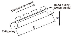
Te= 9.8(μ・G+G・H/C)
- Te (N)
- : Effective tension
- G (kg)
- : Gross weight of the conveyance on the belt
- μ
- : Friction coefficient between table and belt (Table 1)
- H (mm)
- : Lifting height
- C (mm)
- : Tentative distance between shafts (Machine length)
| Table Material | Steel | Stainless Steel | Aluminum | UHMW | Fluoropolymer (Example) |
|---|---|---|---|---|---|
| Friction Coefficient: μ | 0.65 | 0.68 | 0.42 | 0.31 | 0.21 |
[Step 2] Calculate the design tension (Td).
- Td (N)
- : Design tension
- K
- : Overload factor
- Te (N)
- : Effective tension
- K1
- : Correction factor based on operating hours
- K2
- : Correction factor based on belt length
- K3
- : Correction factor based on belt speed
Table 2 K1 Correction Factor Based on Daily Operating Hours
(Unit: hours)
| ~5 | 5~8 | 8~12 | 12~16 | 16~24 |
|---|---|---|---|---|
| 1.0 | 1.1 | 1.2 | 1.3 | 1.4 |
Table 3 K2 Correction Factor Based on Belt Length
(Unit: mm)
| ~1500 | 1501~3000 | 3001~4500 | 4501~ |
|---|---|---|---|
| 0.3 | 0.2 | 0.1 | 0.0 |
Table 4 K3 Correction Factor Based on Belt Speed
(Unit: m/min)
| ~ 60 | 61~90 | 91~120 |
|---|---|---|
| 0.0 | 0.1 | 0.2 |
[Step 3] Select the belt type, belt width and pulley diameter.
(1) Select a belt type and width that has Ta (allowable tension) ≥ Td (design tension) from Table 5 below.
Table 5 Jointed Belt Allowable Tension
(Unit: N)
| Belt Type | Belt Width (mm) | ||||||
|---|---|---|---|---|---|---|---|
| 10 | 15 | 20 | 25 | 30 | 40 | 50 | |
| S5M | 120 | 180 | - | 300 | - | - | - |
| S8M | - | 235 | - | 392 | 471 | 627 | - |
| T5 | 58 | 87 | 116 | 145 | - | - | - |
| T10 | - | 180 | 240 | 300 | 360 | 481 | 601 |
| AT5 | 74 | 110 | - | - | - | - | - |
| AT10 | - | 234 | 312 | 391 | - | - | - |
(Unit: N)
| Belt Type | Belt Nominal Width | ||||
|---|---|---|---|---|---|
| 050 | 075 | 100 | 150 | 200 | |
| L | 92 | 138 | 184 | 276 | - |
| H | - | 163 | 216 | 324 | 432 |
(2) For both the drive and driven pulleys, select those with more teeth than the minimum allowable number of teeth shown in Table 6 below.
Table 6 Minimum Allowable Number of Pulley Teeth
| Belt Type | Pitch (mm) | Minimum Number of Teeth | Pulley Diameter (mm) |
|---|---|---|---|
| L | 9.525 | 14 | 42.45 |
| H | 12.7 | 14 | 56.60 |
| S5M | 5 | 14 | 22.28 |
| S8M | 8 | 24 | 61.12 |
| T5 | 5 | 12 | 19.10 |
| T10 | 10 | 14 | 44.56 |
| AT5 | 5 | 20 | 31.83 |
| AT10 | 10 | 14 | 44.56 |
[Step 4] Determine the belt circumference (number of teeth) and distance between shafts.
(1) Determine the approximate belt circumference based on the tentative distance between shafts (C’) and approximate pulley diameter (Dp’).
- Lp’ (mm)
- : Approximate belt circumference
- C’ (mm)
- : Tentative distance between shafts
- Dp’ (mm)
- : Approximate pulley diameter
(2) Determine the number of belt teeth (N) based on the approximate belt circumference (Lp’) and
pitch (P).
The number of belt teeth (N) should be rounded to the natural number. (Be careful about the
minimal length.)
- N
- : Number of belt teeth
- P (mm)
- : Pitch
(3) Determine the exact belt circumference based on the number of belt teeth (N) and pitch (P).
- Lp (mm)
- : Belt circumference
(4) Determine the exact distance between shafts (C) using the formula below.
- C (mm)
- : Distance between shafts
- Dz
- : Number of pulley teeth
[Step 5] Confirm that the adjustable allowance for distance between shafts is greater than the values shown in Table 7-a and Table 7-b, as applicable.
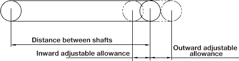
| Belt Type | Inward Adjustable Allowance |
|---|---|
| L | 10 mm or more |
| H | 15 mm or more |
| S5M | 10 mm or more |
| S8M | 15 mm or more |
| T5 | 5 mm or more |
| T10 | 10 mm or more |
| AT5 | 10 mm or more |
| AT10 | 15 mm or more |
| Distance Between Shafts (mm) | Outward Adjustable Allowance |
|---|---|
| ~500 | 5 mm or more |
| 501~1000 | 10 mm or more |
| 1001~1500 | 15 mm or more |
| 1501~2000 | 20 mm or more |
| 2001~2500 | 25 mm or more |
| 2501~ | 1% or more of the distance between shafts |
[Step 6] Tension the belt.
Extend the belt at the installation tension shown in Table 8. The shaft load will be twice the installation tension. Shafts should have sufficient strength.
- Fs (N)
- : Shaft load
- Ti (N)
- : Installation tension (See table below)
Table 8 Jointed Belt Installation Tension
(Unit: N)
| Belt Type | Belt Width (mm) | ||||||
|---|---|---|---|---|---|---|---|
| 10 | 15 | 20 | 25 | 30 | 40 | 50 | |
| S5M | 60 | 90 | - | 150 | - | - | - |
| S8M | - | 117 | - | 196 | 235 | 313 | - |
| T5 | 29 | 43 | 58 | 72 | - | - | - |
| T10 | - | 90 | 120 | 150 | 180 | 240 | 300 |
| AT5 | 37 | 55 | - | - | - | - | - |
| AT10 | 117 | 156 | 195 | - | - | - | - |
(Unit: N)
| Belt Type | Belt Nominal Width | ||||
|---|---|---|---|---|---|
| 050 | 075 | 100 | 150 | 200 | |
| L | 46 | 69 | 92 | 138 | - |
| H | - | 81 | 108 | 162 | 216 |
Reference: Open-End Belt Allowable Tension Table*3
(Unit: N)
| Belt Type | Material | Belt Width (mm) | |||||||
|---|---|---|---|---|---|---|---|---|---|
| 6 | 10 | 15 | 20 | 25 | 30 | 40 | 50 | ||
| S3M | Polyurethane | 127 | - | - | - | - | - | - | - |
| S5M | Rubber | - | 310 | 490 | - | - | - | - | - |
| Polyurethane | 215 | 323 | 539 | ||||||
| S8M | Rubber | - | - | - | - | 950 | - | - | - |
| Polyurethane | 647 | 1176 | 1412 | 1882 | |||||
| T5 | Polyurethane | - | 112 | 166 | 225 | 284 | - | - | - |
| T10 | Polyurethane | - | - | 299 | 397 | 529 | 627 | 862 | 1064 |
| AT5 | Polyurethane | - | 147 | 221 | - | - | - | - | - |
| AT10 | Polyurethane | - | - | 469 | 625 | 781 | - | - | - |
(Unit: N)
| Belt Type | Material | Belt Width (mm) | ||||||
|---|---|---|---|---|---|---|---|---|
| 025 | 037 | 050 | 075 | 100 | 150 | 200 | ||
| XL | Rubber | - | 45 | 70 | - | - | - | - |
| Polyurethane | 66 | 102 | 142 | |||||
| L | Rubber | - | - | 95 | 165 | - | - | - |
| Polyurethane | 259 | 387 | 519 | |||||
| H | Rubber | - | - | - | - | 600 | - | - |
| Polyurethane | 397 | 529 | 799 | 1093 | ||||
Notes
- *1 Head pulley: Pulley located in the forward direction of travel
- *2 Tail pulley: Pulley located behind the direction of travel
- *3 For applications other than conveyance (e.g. transmission), design S3M with approx. 1/2 of the allowable tension in the table and XL, L, H, S5M, S8M, T5 and T10 polyurethane belts with approx. 2/3 of the allowable tension in the table.
PDF list
Payment Method
- Credit Card
- PayPal
- Bank Transfer
Social Media
MISUMI Contact
Copyright © MISUMI Corporation All Rights Reserved.