(!)Due to
Microsoft's end of support for Internet Explorer 11 on 15/06/2022, this site does not support the recommended
environment.
Instead, please kindly use other browsers like Google Chrome, Microsoft Edge or Mozilla
Firefox.
- Please be informed that there will be no shipment from Japan during the upcoming year-end and New Year holiday period. However, Singapore’s stock items are available during these periods. More details.
- Notice of End of Sales for Economy Series Pneumatic Equipment Category. More details.
Spring Calculations (Excerpt from JIS B 2701-1:2018)
- Symbols Used in Spring Design Equations
- Basic Formula Used in Spring Design
- Matters for Consideration in Spring Design
Symbols Used in Spring Design Equations
Symbol meaning
| Symbol | Symbol meaning | Unit |
|---|---|---|
| c | Spring index c = D/d | ー |
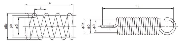
| D | Average coil diameter D = (Di + De)/2 | mm |
| De | Coil outer diameter | mm |
| Di | Coil inner diameter | mm |
| d | Wire diameter (wire diameter to be used in calculation or diameter of product material) | mm |
| F | Spring force or force acting on spring (load) | N |
| Fi | Initial tension of tension spring | N |
| fe | Natural frequency | Hz |
| G | Modulus of transverse elasticity | N/mm2 |
| Lc | Closed length of compression spring | mm |
| Lo | Custom length of compression spring or custom length of tension spring | mm |
| ms | Weight of spring moving parts | kg |
| n | Effective number of coils of compression spring or number of coils of tension spring | ー |
| nt | Total number of coils | ー |
| p | Spring pitch | mm |
| R | Spring constant of compression spring and tension spring | N/mm |
| s | Deflection of compression spring and tension spring | mm |
| U | Energy stored in spring | J |
| κ | Shear stress correction factor | ー |
| ρ | Weight per unit volume of material (density) | kg/mm3 |
| σB | Tensile strength of material | N/mm2 |
| Τκ | Shear correction stress | N/mm2 |
| Τo,i | Initial shear non-correction stress of tension spring | N/mm2 |
| Τo | Shear non-correction stress of compression spring or tension spring | N/mm2 |
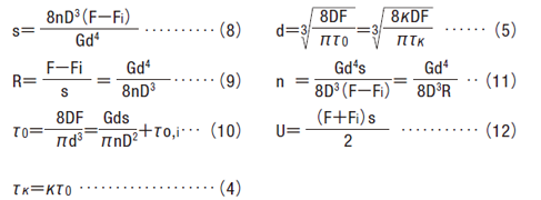
Basic Formula Used in Spring Design
When designing compression springs
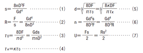
When designing tension springs with initial tension When there is no initial tension Fi = to, i = 0
Matters for Consideration in Spring Design
Modulus of transverse elasticity (main materials)
Unit: N/mm2
| Material | G value | |
|---|---|---|
| Spring steel material Hard steel wire Piano wire Oil tempered wire |
7.85x10⁴ | |
| Stainless steel wire for springs | SUS302 SUS304 SUS304n1 SUS316 |
6.85x10⁴ |
| SUS631J1 | 7.35x10⁴ | |
| Brass wire Nickel silver wire |
3.90x10⁴ | |
| Phosphor bronze wire | 4.20x10⁴ | |
| Beryllium copper wire | 4.40x10⁴ | |
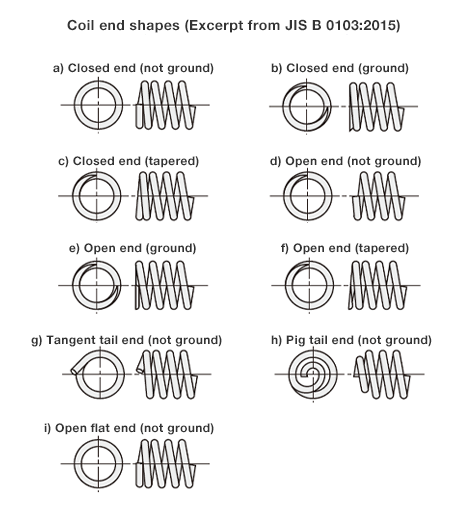
Effective number of coils
The effective number of coils used in spring design depends on the following.
Characteristics can become unstable when using less than three effective coils, and so more than three should be used.
For compression springs
For compression springs, the effective number of coils depends on the following.
n=nt-(X1+X2)
X1 and X2 is the number of end coils at each end of the coil
a) When the coil end is an end shape touching the next coil, and each end coil has one coil (equivalent to the end shapes (a)-(c))
X1=X2=1
As such, n = nt-2
b) When the coil end is an end shape not touching the next coil, and each coil has 0.75 coils (equivalent to the end shapes (e) to (f))
X1=X2=0.75
As such, n = nt-1.5
For tension springs
For tension springs, the effective number of coils depends on the following. However, the hook part is excluded.
n=nt
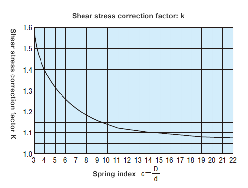
Stress correction factor
The shear stress correction factor for the spring index c value depends on the following formula or figure.

Closed length of compression spring
The closed length of compression springs can generally be calculated using the following simplified formula.
However, the closed length of compression springs must only be a reference.

t1 + t2 is the sum of the thickness of both coil ends
If both ends of a compression spring have been ground or tapered, and especially when closed length must be specified, the value obtained from the following formula can be used as the maximum closed length. However, caution is required as, depending on the spring shape, the closed length could be larger than this value.

Initial tension of tension spring
Tension springs with solid coiling can cause initial tension Fi.
The initial tension can be calculated using the following formula.

When steel wire such as piano wire and hard steel wire has been formed into solid coiling but not undergone low temperature annealing, initial shear non-correction stress To,i shall be within the two diagonal lines in the figure below. However, when using wire other than steel wire and carrying out low temperature annealing, initial shear non-correction stress To,i taken from between the two diagonal lines below can be corrected as follows.

- (1)When using stainless steel spring wire, it shall be 15% lower than the initial shear non-correction stress of steel wire.
- (2)When carrying out low temperature annealing after the wire has been formed, it shall be 20 to 35% lower for piano wires, hard steel wires, and other steel wires, and 15 to 25% lower for stainless steel spring wires, than the values obtained above. As an alternative to obtaining the pre-low temperature annealing initial shear non-correction stress To,i from the above figure, it can also be calculated using the following empirical formula.

An example of a calculation formula used to calculate initial tension Fi through this formula is shown below.
For piano wires and hard wires [G = 7.85 × 10⁴ (N/mm2)]

For stainless steel spring wires [G = 6.85 × 10⁴ (N/mm2)]

Compression spring and tension spring surging
To avoid surging, the spring’s natural frequency must be selected so that it does not resonate with vibrations from the vibration source that act on the spring.
The spring’s natural frequency can be calculated using the following formula.

When both ends of compression springs and tension springs made of G = 7.85 × 10⁴ (N/mm2) material or ρ = 7.85 × 10⁻⁶ (kg/mm3) material (such as piano wires) are either free or fixed, the spring’s first-stage natural frequency is calculated using the following formula.

Other matters for consideration
The following must also be taken into consideration for spring design equations.
(1) Spring index
As spring index gets smaller, local stress becomes excessive. Workability also becomes problematic when spring index gets either bigger or smaller. As such, when forming springs in a hot environment, spring index should be between 4 and 15, and when forming in a cold environment, spring index should be between 3 and 22.
(2) Aspect ratio
The aspect ratio (ratio of custom length to average coil diameter) of compression springs should be 0.8 or greater to maintain the effective number of coils, and 4 or below to prevent buckling.
(3) Pitch
If the pitch exceeds 0.5 D, coil diameter generally changes in line with an increase in force (load). This requires the deflection and shear stress obtained from the basic formula to be corrected, and so pitch should be kept at 0.5 D or below. General pitch estimations can be calculated using the following simplified formula.

PDF list
Payment Method
- Credit Card
- PayPal
- Bank Transfer
Social Media
MISUMI Contact
Copyright © MISUMI Corporation All Rights Reserved.