(!)Due to
Microsoft's end of support for Internet Explorer 11 on 15/06/2022, this site does not support the recommended
environment.
Instead, please kindly use other browsers like Google Chrome, Microsoft Edge or Mozilla
Firefox.
- Labour Day & Japan Golden Week Holiday Notice: Some suppliers will be on extended holidays during this period. Lead times may be longer than usual. Please check the updated lead times on our website before placing your order. More details
- Notice of End of Sales for Economy Series Pneumatic Equipment Category. More details.
Design of chain drive mechanism 2
Selection method for low speed case
At a low chain speed of 50m/min or less, it is hardly necessary to consider stretching due to chain friction, and lifespan will be mainly determined by fatigue strength. In this case, selection of a low speed setting method is permitted rather than the “general case selection method”. The low-speed selection method is used for the case of a smooth transmission with few starts and stops, and the atmosphere, placement and lubrication etc all comply with the general case.
| Roller chain speed | Speed factor |
|---|---|
| 0~15 m/min | 1.0 |
| 15~30 | 1.2 |
| 30~50 | 1.4 |
| 50~70 | 1.6 |
-
(1) Grasp of usage conditions
Same as [General case selection method]. -
(2) Selection of chain and no. of small sprocket teeth
From Table 3 Simple Selection Table choose a slightly smaller chain and sprocket from the rotational speed (r/min) and motor (kW). -
(3) Calculation of chain speed

- V
- : Chain speed (m/min)
- P
- : Chain pitch (mm)
- N
- : No. of sprocket teeth
- n
- : Sprocket rotational speed (r/min)
-
(4) Calculation of chain maximum acting load
Finds the maximum load acting on the chain.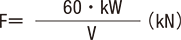
- F
- : Load on the chain (kN)
- V
- : Chain speed (m/min)
- kW
- : Power transmission (kW)
-
(5) Decision on used factors
The used factors are found from the Used factors table (Table 1). -
(6) Decision on speed factors
Finds the speed factor from the chain speed calculated in (3). -
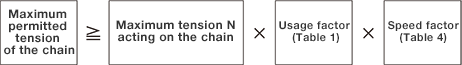
(7) Study of maximum allowable tension of the chain
Substitute the values found in (4) - (6) in the selected formula, compare the result with the maximum allowable tension of the chain selected in (2) and consider if it satisfies the selection formula.
If not satisfied, change the chain and sprocket and consider again. -
(8) Check of the no. of teeth and shaft diameter of the large sprocket,
and calculate the chain length
The selection below is the same as “General case selection method”.
Selection method when impact load acts at low speed
Under conditions where there are many sudden start/stops, or reverse braking or braking, and the
action of many impact loads, the inertia (GD2) of the motor or non-motor must be taken into
account.
Compared with the general transmission case, sufficient care is required because a rather large
load is acting on the chain.
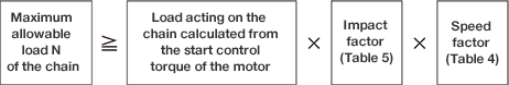
Impact factor
The constants determined by the inertia ratio (GD2 ratio) of the motor and the driven machinery
and the size of the motor play are shown in (Table 5). Note that where the play is extremely
large, an impact larger than that value may be acting.

Selection method of the stainless steel roller chain (CHES)
Please used the low speed selection method as the stainless steel roller chain selection method.
- 1) Maximum allowable tension is lower for CHES (stainless steel type) compared to the CHE (steel type) roller chain.
- 2) Please avoid use of the offset link as far as possible.
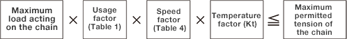
Temperature selection method
Roller chain temperature selection method
This is the size selection method anticipating reduction in strength due to temperature.
-
1)
Problems with roller chain transmission at high temperatures
(1) Increased friction due to decline in hardness
(2) Increased stretch due to hardening
(3) Oiling defects and flex defects due to oil deterioration and carbonization, increased friction
(4) Increased friction and flex defects due to occurrence of scale -
2)
Problems with roller chain transmission at low temperatures
(1) Decline in impact strength due to low temperature brittleness
(2) Coagulation in the lubricant oil
(3) Faulty flex due to snow or ice attached
| Temperature | CHE Roller chain | |
|---|---|---|
| Less than CHE60 | Greater than CHE80 | |
| Less than −60℃ | − | − |
| Greater than -60℃ to -50℃ | − | − |
| Greater than -50℃ to -40℃ | − | Not used |
| Greater than -40℃ to -30℃ | Not used | Catalog value × 1/4 |
| Greater than -30℃ to -20℃ | Catalog value × 1/4 | Catalog value × 1/3 |
| Greater than -20℃ to -10℃ | Catalog value × 1/3 | Catalog value × 1/2 |
| Greater than -10℃ to 60℃ | Catalog value | Catalog value |
| Greater than 60℃ to 150℃ | Catalog value | Catalog value |
| Greater than 150℃ to 200℃ | Catalog value × 3/4 | Catalog value × 3/4 |
| Greater than 200℃ to 250℃ | Catalog value × 1/2 | Catalog value × 1/2 |
| Above 250℃ | Not used | Not used |
Selection method at high temperature of stainless steel roller chain
(1) Up to 400℃ use the low speed selection method. (General selection method cannot be
used.)
(2) Above 400℃ use the temperature factor shown in the table below.
(3) Selection method
| Temperature | Factor (Kt) |
|---|---|
| Less than 400℃ | 1.0 |
| Greater than 400℃ to 500℃ | 1.2 |
| Greater than 500℃ to 600℃ | 1.5 |
| Greater than 600℃ to 700℃ | 1.8 |
| Above 700℃ | Not used |
Corrosion resistance decreases above 400℃, so please take that into consideration in selection.
Conversion of output and torque
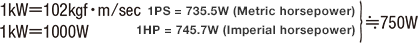
- Torque:
- 1kg・m=100kg・cm
- 1kg・m=9.8N・m (Newton torque)
- 1N・m=0.120kg・m
- 1r/min =1rpm
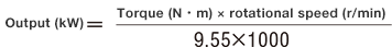
When displayed as a combination of torque and rotational speed
PDF list
Payment Method
- Credit Card
- PayPal
- Bank Transfer
Social Media
MISUMI Contact
Copyright © MISUMI Corporation All Rights Reserved.