(!)Due to
Microsoft's end of support for Internet Explorer 11 on 15/06/2022, this site does not support the recommended
environment.
Instead, please kindly use other browsers like Google Chrome, Microsoft Edge or Mozilla
Firefox.
- Labour Day & Japan Golden Week Holiday Notice: Some suppliers will be on extended holidays during this period. Lead times may be longer than usual. Please check the updated lead times on our website before placing your order. More details
- Notice of End of Sales for Economy Series Pneumatic Equipment Category. More details.
Design of chain transmission mechanism
Selection of power transmission
The power transmission table has the following items as conditions.
1) Operated in temperatures in the range −10℃~+60℃, in environments where there
is no
abrasive dust.
2) No bad impact from corrosive gas or high humidity.
3) The transmitting 2 shafts are horizontal and suitably located and
placed.
4) Recommended oiling format and lubricant oil are used.
5) Transmission with little variation in load.
Usage factor table
The power transmission table assumes conditions of little load variation, so power transmission kW are adjusted depending on the size of the load variation.
| Impact types | Example of machines used | Motor classification | ||
|---|---|---|---|---|
| Motor turbine | Internal combustion engine | |||
| With fluid mechanics | No fluid mechanics | |||
| Smooth transmission | Belt conveyors with low load variation, chain conveyors, centrifugal pumps, centrifugal blowers, general purpose spinning machines, general purpose machinery with low load variation | ×1.0 | ×1.0 | ×1.2 |
| Transmission with moderate impact | Centrifugal compressors, marine propellers, conveyors with some load fluctuations, automatic furnaces, dryers, crushers, general machine tools, compressors, general civil or building machinery, general papermill machinery | ×1.3 | ×1.2 | ×1.4 |
| Transmission with large impact | Presses, crushers, mining machines, vibrating machines, oil drilling machinery, rubber mixers, rolls, roll gangs, reversing or impact-loaded general machines | ×1.5 | ×1.4 | ×1.7 |
Multi-row factor table
With the power transmission of multi-row roller chains, the load on each row of the chain is not evenly spread, so the power of a multiple of rows of a single row roller chain cannot be anticipated. Therefore, the power transmission of the multi-row roller chain is found by multiplying the 1-row roller chain transmission power by the multi-row factor.
| Roller chain factor | Multi-row factor |
|---|---|
| 2 rows | ×1.7 |
| 3 rows | ×2.5 |
| 4 rows | ×3.3 |
| 5 rows | ×3.9 |
| 6 rows | ×4.6 |
Simple selection table
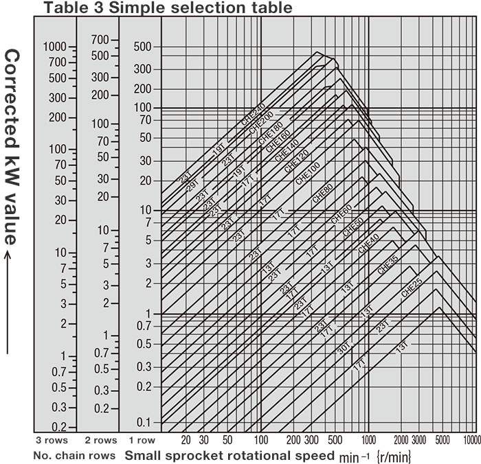
Explanation of the table
Example:
Where corrected kW=5kW, small sprocket rotational speed= 300r/min with 1 row chain
The intersection point of corrected kW (vertical axis) and the rotational speed of 300r/min
(horizontal axis) is CHE60 in the range fewer than 23T, but more than 17T. The manufacturer
determines from the intersection point that 19T can be used.
General case selection method
-
(1) Grasp of usage conditions
The following 7 conditions for roller chain selection should be understood.
1. Machines used
2. Impact types
3. Motor classification
4. Power transmission (kW)
5. Shaft diameter and rotational speed of high-speed shaft
6. Shaft diameter and rotational speed of low speed shaft
7. Distance between shafts -
(2) Decision on usage factors
The usage factor is decided based on the Usage factor table (Table 1), according to the machine transmitting power or the motor type. -
(3) Decision on corrected power transmission (kW)
Power transmission (kW) is corrected by the usage factor.
・In single-row chain case…Corrected power transmission (kW) = power transmission (kW) × usage factor
・In a multi-row chain case...the multi-row factor is determined from the Multi-row factor table (Table 2).
-
(4) Selection of chain and no. of sprocket teeth
Find the chain and the no. of small sprocket teeth that satisfy the rotational speed of the high speed shaft and the correct power transmission (kW) using the Simple selection table (Table 3) or the Power transmission table. In that case, select the chain with the smallest pitch and the required power transmission. Selecting a chain with the smallest pitch possible will permit smooth transmission with little noise. (If power is insufficient with a single-row chain, select a multi-row chain. Further, if there are mounting space restrictions, and you wish to keep the shaft distance short or the sprocket outer diameter as small as possible, please use a multi-row chain with a small pitch.) Note that the wind angle of the small sprocket and the chain should be greater than 120°. -
(5) Selection of no. of large sprocket teeth
No. of large sprocket teeth = no. small sprocket teeth × velocity ratio Once the no. of small sprocket teeth is decided, this is multiplied by the velocity ratio to determine the no. of large sprocket teeth. Generally, 17 teeth for a small sprocket, more than 21 teeth for a high-speed sprocket and more than 12 teeth for a low speed sprocket is appropriate, and large sprockets with more than 120 teeth are not desirable. However if the velocity ratio is 1:1 or 2:1, a sprocket with large no. of teeth should be selected. Normally, a velocity ratio of 1:7, if possible around 1:5 should be used. -
(6) Shaft diameter check
Check whether the selected small sprocket can be used with the required shaft diameter. Refer to the Standards Table on this page of the Catalog. When larger than the boss diameter, increase the no. of teeth, or select an even larger chain. -
(7) Sprocket distance between shafts
While the shortest distance between shafts may be a distance where 2 sprockets do not touch, please set the wind angle of the small sprocket to more than 120°.
In general the desired distance between shafts is 30 - 50 times the pitch of the chain used, but it can not be a factor of more than 20 when a pulsating load is active. -
(8) Calculation of the chain length and the sprocket center distance
between shafts
The chain length is determined from the formula for number of chain links once the chain and the no. of teeth of both sprockets, and the distance between shafts has been decided.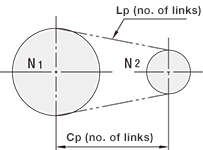
- Lp
- : Expresses the chain length as a number of links
- N1
- : No. of large sprocket teeth
- N2
- : No. of small sprocket teeth
- Cp
- : Expresses the center distance between shafts as a number of links
- π
- : ≒3.14
(1) Calculation of the chain length (when no. of sprocket teeth N1 and N2, and the center distance between shafts Cp are fixed)
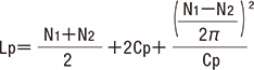
*Round up any decimal places in the Lp value.
Generally, a chain length with an even number of links should be selected. Where the number of links must be odd due to the relation between the shaft distance, an offset link must be used, so as far as possible please use an even number of links by changing the no. of sprocket teeth or the shaft distance.
(2) Calculation of the center distance between shafts (when no. of sprocket teeth N1 and N2, and the chain length Lp are decided)
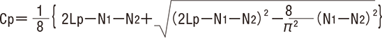
The pitch number obtained from the roller chain required length calculation is almost always an approximation, matching an optional distance between shafts, so the center distance from both shafts is re-calculated precisely from the required overall length.
Example of selection using general selection method
A 3.7kW, 1,000r/min motor, driven by a compressor.
(1) Grasp of usage conditions
1) Used machine: compressor, operating for 10 hours
2) Impact type: smooth transmission
3) Motor type: Motor
4) Power transmission (kW): 3.7kW
5) Rotational speed: 1,000r/min
(2) Decision on usage factors
From Table 1, make usage factor 1.2.
(3) Decision on corrected power transmission (kW)
Corrected power transmission (kW) = power transmission (kW) × usage factor
=3.7kW×1.2=4.44kW
(4) Selection of chain and no. of sprocket teeth
For 1,000r/min、4.44kW, looking at Table 3 Simple selection table, we know that the chain is
CHE40 and the sprocket is 17T.
Checking the power transmission of the CHE40 chain, the power transmission with 13T teeth at
1000 r/min is 4.09kW, which does not satisfy the corrected power transmission, so we then set
the no. of sprocket teeth to 19T, which gives a power transmission of 4.6kW, thus permitting
selection as transmission is possible.
As a result the manufacturer selects, the chain = CHE40
No. of small sprocket teeth = 19T
PDF list
Payment Method
- Credit Card
- PayPal
- Bank Transfer
Social Media
MISUMI Contact
Copyright © MISUMI Corporation All Rights Reserved.