(!)Due to
Microsoft's end of support for Internet Explorer 11 on 15/06/2022, this site does not support the recommended
environment.
Instead, please kindly use other browsers like Google Chrome, Microsoft Edge or Mozilla
Firefox.
- Notice of End of Sales for Economy Series Pneumatic Equipment Category. More details.
How to Select Ball Screws: Page 2
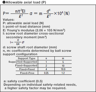
4. Allowable Axial Load
Allowable axial load is a load that ensures safety, calculated taking into account the buckling
load, which is a load that may cause the screw thread section to buckle.
The maximum axial load applied to the screw thread must be equal to or less than the allowable
axial load.
Allowable axial load can be calculated using the formula below.
Alternatively, Table 1 may be used to easily check the allowable axial load based on screw
thread diameter by reading the value indicated by the allowable axial load line.
Example of Calculating Allowable Axial Load
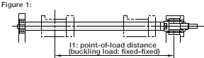
Calculate the allowable axial load based on the conditions in Figure 1.
Usage conditions:
- Screw thread diameter is φ15, lead is 5
- Mounting configuration is fixed–fixed
- Point-of-load distance (ℓ1) is 820 mm
- Screw root diameter (d) is 12.5
Calculation:
Because a fixed–fixed mounting configuration is used, m is 19.9, and allowable axial
load P is calculated as follows:
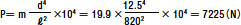
Therefore, the maximum axial load is 7,225 N.
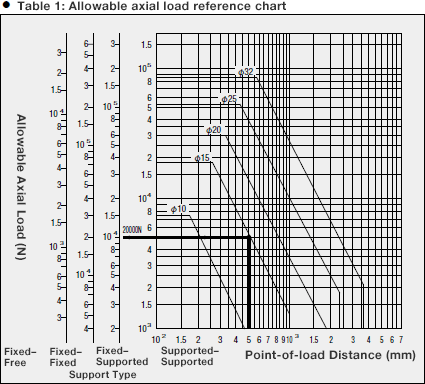
Example of calculating Screw Thread Diameter to Meet Usage Conditions
Usage conditions:
- Point-of-load distance is 500 mm
- Mounting configuration is fixed–fixed
- Maximum axial load is 20,000 N
Selection:
(1) Using Table 1, confirm the point of intersection when using the vertical line
for a 500-mm point-of-load distance and the horizontal line for an allowable axial
load of 20,000 N with a “fixed–supported” support configuration.
(2) The point at which these lines intersect indicates that an allowable thread
diameter of 15 mm or more should be selected.
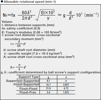
5. Allowable Rotational Speed
The ball screw’s rotational speed is determined based on the required feed rate and ball screw
lead, and must be equal to or less than the allowable rotational speed.
The allowable rotational speed is determined based on two considerations: the critical speed of
the rotary shaft and the rotational speed limit (DmN value) for the ball that rotates within the
nut.
5-1. Critical Speed
The ball screw’s allowable rotational speed is 80% of the critical speed at which the ball
screw’s rotational speed resonates with the natural frequency of the screw shaft.
Allowable rotational speed can be calculated using the formula below.
Alternatively, Table 2 may be used to easily confirm the allowable rotational speed based on
screw thread diameter by reading the value indicated by the allowable rotational speed line.
Example of Calculating Allowable Rotational Speed
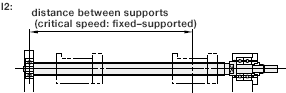
Calculate the allowable rotational speed based on the conditions in Figure 2.
Usage conditions:
- Screw thread diameter is φ15, lead is 5
- Mounting configuration is fixed–supported
- Point-of-load distance (l2) is 790 mm
Calculation:
Because a fixed–supported mounting configuration is used, g is 15.1, and
allowable
rotational speed Nc is calculated as follows:

Therefore, the maximum rotational speed is 3,024 min-1.
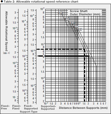
Example of Calculating Allowable Rotational Speed
Usage conditions:
- Screw shaft outer diameter is 20
- Distance between supports is 1,500 mm
- Mounting configuration is fixed–supported
Calculation:
(1) Using Table 1, check the point of intersection when using the vertical line for
a distance between supports of 1,500 mm and the horizontal line for a screw shaft
outer diameter of φ20.
(2) The point at which these lines intersect for a fixed–supported configuration
indicates an allowable rotational speed of 1,076 min-1.
Example of calculating Screw Thread Diameter to Meet Usage Conditions
Usage conditions:
- Distance between supports is 2,000 mm
- Maximum rotational speed is 1,000 min-1
- Mounting configuration is fixed–fixed
Calculation:
(1) Using Table 2, confirm the point of intersection when using the vertical line
for a distance between supports of 2,000 mm and the horizontal line for an allowable
rotational speed of 1,000 min-1 with a “fixed–fixed” support
configuration.
(2) The point at which these lines intersect indicates a shaft diameter tolerance
value of 25 mm, which fulfills the diameter requirement for a maximum rotational
speed of 1,000 min-1.
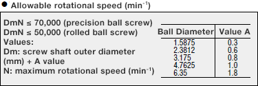
5-2. DmN Value
The higher the orbital speed of the steel balls within the nut, the greater the impacting force
applied to the rotating section, resulting in damage to it.
The relevant threshold value is known as the DmN value.
It can be calculated as follows.
PDF list
Payment Method
- Credit Card
- PayPal
- Bank Transfer
Social Media
MISUMI Contact
Copyright © MISUMI Corporation All Rights Reserved.