(!)Due to
Microsoft's end of support for Internet Explorer 11 on 15/06/2022, this site does not support the recommended
environment.
Instead, please kindly use other browsers like Google Chrome, Microsoft Edge or Mozilla
Firefox.
- Scheduled Maintenance Notice: This site will be unavailable due to scheduled maintenance from 15:00 5/4/2026 to 7:00 (SGT) 6/4/2026. We apologize for the inconvenience.
- Please be informed that our operating hours on Hari Raya Puasa will be from 9:00 AM to 3:00 PM. Our office will be closed on 3 April 2026 in observance of the Good Friday holiday. More details.
- Notice of End of Sales for Economy Series Pneumatic Equipment Category. More details.
Spring Pins (Excerpt from JIS B 2808:2013)
Shapes and Dimensions of General Load Slotted Spring Pins
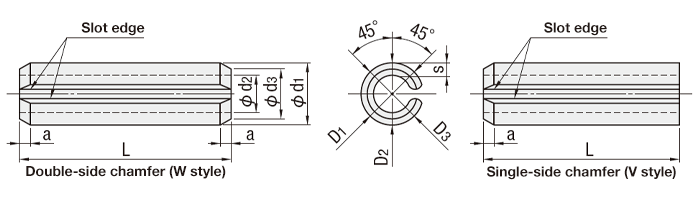
The diameter of the spring pin mounting hole is the same as the nominal diameter of the spring
pin. The dimensional tolerance of the mounting hole is H12 as regulated in JIS B 0401-1.
When inserting the spring pin into the mounting hole, the slot edge must not be in contact with
the entire surface.
There is no chamfering amount (a) standard for general load slotted spring pins.
Notes
- The outer diameter of slotted spring pins depends on the following.
- Maximum value of outer diameter d1: The maximum value of the outer diameter on the pin circumference.
- Minimum value of outer diameter d1: The average outer diameter value of D1, D2, and D3 on the pin circumference.
General load
Unit: μm
| Nominal diameter | 1 | 1.2 | 1.4 | 1.5 | 1.6 | 2 | 2.5 | 3 | |
|---|---|---|---|---|---|---|---|---|---|
| Pre-mount d1 | Max. | 1.2 | 1.4 | 1.6 | 1.7 | 1.8 | 2.25 | 2.75 | 3.25 |
| Min. | 1.1 | 1.3 | 1.5 | 1.6 | 1.7 | 2.15 | 2.65 | 3.15 | |
| Chamfer diameter d3 | Max. | 0.9 | 1.1 | 1.3 | 1.4 | 1.5 | 1.9 | 2.4 | 2.9 |
| Thickness s | 0.2 | 0.25 | 0.28 | 0.3 | 0.3 | 0.4 | 0.5 | 0.6 | |
| Shear strengtha) Minimum value (kN) |
0.69 | 1.02 | 1.35 | 1.55 | 1.68 | 2.76 | 4.31 | 6.2 | |
| Mounting hole | 1 | 1.2 | 1.4 | 1.5 | 1.6 | 2 | 2.5 | 3 | |
| Dimensional tolerance (H12) | +0.10 0 |
||||||||
| Nominal diameter | 4 | 5 | 6 | 8 | 10 | 13 | |
|---|---|---|---|---|---|---|---|
| Pre-mount d1 | Max. | 4.4 | 5.4 | 6.4 | 8.6 | 10.6 | 13.7 |
| Min. | 4.2 | 5.2 | 6.2 | 8.3 | 10.3 | 13.4 | |
| Chamfer diameter d3 | Max. | 3.9 | 4.8 | 5.8 | 7.8 | 9.8 | 12.7 |
| Thickness s | 0.8 | 1.0 | 1.2 | 1.6 | 2.0 | 2.5 | |
| Shear strengtha) Minimum value (kN) |
10.8 | 17.25 | 24.83 | 44.13 | 68.94 | 112.78 | |
| Mounting hole | 4 | 5 | 6 | 8 | 10 | 13 | |
| Dimensional tolerance (H12) | +0.12 0 |
+0.15 0 |
+0.18 0 |
||||
| Length Lb) | Allowable tolerance | Nominal diameter | |||||||||||||
|---|---|---|---|---|---|---|---|---|---|---|---|---|---|---|---|
| 1 | 1.2 | 1.4 | 1.5 | 1.6 | 2 | 2.5 | 3 | 4 | 5 | 6 | 8 | 10 | 13 | ||
| 4 | +0.5 0 |
○ | ○ | ○ | ○ | ○ | |||||||||
| 5 | ○ | ○ | ○ | ○ | ○ | ○ | ○ | ||||||||
| 6 | ○ | ○ | ○ | ○ | ○ | ○ | ○ | ○ | |||||||
| 8 | ○ | ○ | ○ | ○ | ○ | ○ | ○ | ○ | ○ | ||||||
| 10 | ○ | ○ | ○ | ○ | ○ | ○ | ○ | ○ | ○ | ○ | |||||
| 12 | +1.0 0 |
○ | ○ | ○ | ○ | ○ | ○ | ○ | ○ | ○ | ○ | ||||
| 14 | ○ | ○ | ○ | ○ | ○ | ○ | ○ | ○ | ○ | ||||||
| 16 | ○ | ○ | ○ | ○ | ○ | ○ | ○ | ○ | |||||||
| 18 | ○ | ○ | ○ | ○ | ○ | ○ | ○ | ○ | |||||||
| 20 | ○ | ○ | ○ | ○ | ○ | ○ | ○ | ○ | |||||||
| 22 | ○ | ○ | ○ | ○ | ○ | ○ | ○ | ○ | |||||||
| 25 | ○ | ○ | ○ | ○ | ○ | ○ | ○ | ○ | |||||||
| 28 | ○ | ○ | ○ | ○ | ○ | ○ | ○ | ||||||||
| 32 | ○ | ○ | ○ | ○ | ○ | ○ | ○ | ||||||||
| 36 | ○ | ○ | ○ | ○ | ○ | ○ | |||||||||
| 40 | ○ | ○ | ○ | ○ | ○ | ○ | |||||||||
| 45 | ○ | ○ | ○ | ○ | ○ | ||||||||||
| 50 | ○ | ○ | ○ | ○ | ○ | ||||||||||
| 56 | +1.5 0 |
○ | ○ | ○ | ○ | ||||||||||
| 63 | ○ | ○ | ○ | ○ | |||||||||||
| 70 | ○ | ○ | ○ | ||||||||||||
| 80 | ○ | ○ | ○ | ||||||||||||
| 90 | ○ | ○ | |||||||||||||
| 100 | ○ | ○ | |||||||||||||
| 110 | ○ | ||||||||||||||
| 125 | ○ | ||||||||||||||
| 140 | ○ | ||||||||||||||
Explanatory note Recommended lengths are shown within the bold lines.
Notes
PDF list
Payment Method
- Credit Card
- PayPal
- Bank Transfer
Social Media
MISUMI Contact
Copyright © MISUMI Corporation All Rights Reserved.