(!)Due to
Microsoft's end of support for Internet Explorer 11 on 15/06/2022, this site does not support the recommended
environment.
Instead, please kindly use other browsers like Google Chrome, Microsoft Edge or Mozilla
Firefox.
- Please be informed that there will be no shipment from Japan during the upcoming year-end and New Year holiday period. However, Singapore’s stock items are available during these periods. More details.
- Notice of End of Sales for Economy Series Pneumatic Equipment Category. More details.
Sunk Keys and Keyways (excerpt from JIS B 1301:1996)
Parallel Keys and keyways*1
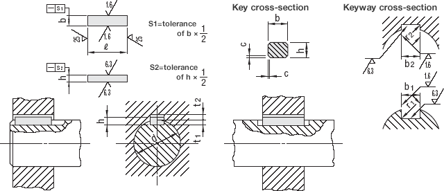
(Unit: mm)
| Nominal dimensions of key b × h |
Keyway dimensions | Reference | |||||||||
|---|---|---|---|---|---|---|---|---|---|---|---|
| Standard dimensions of b1 and b2 |
(Sliding style) | Middle | Fine | r1 and r2 | Standard dimensions of t1 |
Standard dimensions of t2 |
Allowable tolerance of t1 and t2 |
Compatible shaft diameter d *2 |
|||
| b1 | b2 | b1 | b2 | b1 and b2 | |||||||
| Allowable tolerance (H9) |
Allowable tolerance (D10) |
Allowable tolerance (N9) |
Allowable tolerance (Js9) |
Allowable tolerance (P9) |
|||||||
| 2×2 | 2 | +0.025 0 |
+0.060 +0.020 |
-0.004 -0.029 |
±0.0125 | -0.006 -0.031 |
0.08~0.16 | 1.2 | 1.0 | + 0.1 0 |
6~8 |
| 3×3 | 3 | 1.8 | 1.4 | 8~10 | |||||||
| 4×4 | 4 | +0.030 0 |
+0.078 +0.030 |
0 -0.030 |
±0.0150 | -0.012 -0.042 |
2.5 | 1.8 | 10~12 | ||
| 5×5 | 5 | 0.16~0.25 | 3.0 | 2.3 | 12~17 | ||||||
| 6×6 | 6 | 3.5 | 2.8 | 17~22 | |||||||
| (7×7) | 7 | + 0.036 0 |
+0.098 +0.040 |
0 -0.036 |
±0.0180 | -0.015 -0.051 |
4.0 | 3.0 | +0.2 0 |
20~25 | |
| 8×7 | 8 | 4.0 | 3.3 | 22~30 | |||||||
| 10×8 | 10 | 0.25~0.40 | 5.0 | 3.3 | 30~38 | ||||||
| 12×8 | 12 | +0.043 0 |
+0.120 +0.050 |
0 -0.043 |
±0.0215 | -0.018 -0.061 |
5.0 | 3.3 | 38~44 | ||
| 14×9 | 14 | 5.5 | 3.8 | 44~50 | |||||||
| (15×10) | 15 | 5.0 | 5.0 | 50~55 | |||||||
| 16×10 | 16 | 6.0 | 4.3 | 50~58 | |||||||
| 18×11 | 18 | 7.0 | 4.4 | 58~65 | |||||||
| 20×12 | 20 | +0.052 0 |
+0.149 +0.065 |
0 - 0.052 |
±0.0260 | -0.022 -0.074 |
0.40~0.60 | 7.5 | 4.9 | 65~75 | |
| 22×14 | 22 | 9.0 | 5.4 | 75~85 | |||||||
| (24×16) | 24 | 8.0 | 8.0 | 80~90 | |||||||
| 25×14 | 25 | 9.0 | 5.4 | 85~95 | |||||||
| 28×16 | 28 | 10.0 | 6.4 | 95~110 | |||||||
| 32×18 | 32 | +0.062 0 |
+0.180 +0.080 |
0 - 0.062 |
±0.0310 | -0.026 -0.088 |
11.0 | 7.4 | 110~130 | ||
| (35×22) | 35 | 0.70~1.00 | 11.0 | 11.0 | +0.3 0 |
125~140 | |||||
| 36×20 | 36 | 12.0 | 8.4 | 130~150 | |||||||
| (38×24) | 38 | 12.0 | 12.0 | 140~160 | |||||||
| 40×22 | 40 | 13.0 | 9.4 | 150~170 | |||||||
| (42×26) | 42 | 13.0 | 13.0 | 160~180 | |||||||
| 45×25 | 45 | 15.0 | 10.4 | 170~200 | |||||||
| 50×28 | 50 | 17.0 | 11.4 | 200~230 | |||||||
| 56×32 | 56 | +0.074 0 |
+0.220 +0.100 |
0 - 0.074 |
±0.0370 | -0.032 -0.106 |
1.20~1.60 | 20.0 | 12.4 | 230~260 | |
| 63×32 | 63 | 20.0 | 12.4 | 260~290 | |||||||
| 70×36 | 70 | 22.0 | 14.4 | 290~330 | |||||||
| 80×40 | 80 | 2.00~2.50 | 25.0 | 15.4 | 330~380 | ||||||
| 90×45 | 90 | +0.087 0 |
+0.260 +0.120 |
0 - 0.087 |
±0.0435 | -0.037 -0.124 |
28.0 | 17.4 | 380~440 | ||
| 100×50 | 100 | 31.0 | 19.5 | 440~500 | |||||||
Taper Keys, gib-headed taper keys, and keyways*3
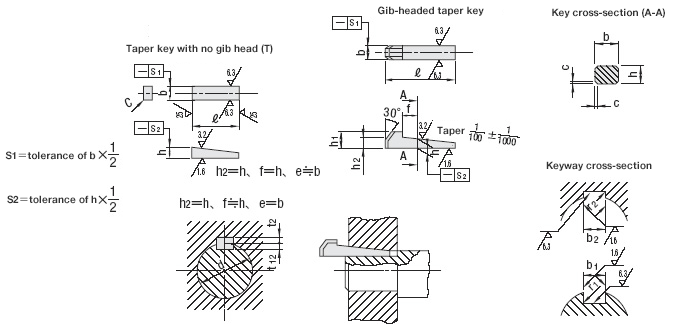
(Unit: mm)
| Nominal dimensions of key b × h |
Key dimensions | Keyway dimensions | Reference | ||||||||||||
|---|---|---|---|---|---|---|---|---|---|---|---|---|---|---|---|
| b | h | h1 | c | ℓ *4 | b1 and b2 | r1 and r2 | Standard dimensions of t1 |
Standard dimensions of t2 |
Allowable tolerance of t1 and t2 |
Compatible shaft diameter d *5 |
|||||
| Standard dimensions |
Allowable tolerance (h9) |
Standard dimensions |
Allowable tolerance |
Standard dimensions |
Allowable tolerance (D10) |
||||||||||
| 2×2 | 2 | 0 - 0.025 |
2 | 0 - 0.025 |
h9 | - | 0.16 ~0.25 |
6~30 | 2 | +0.060 +0.020 |
0.08 ~0.16 |
1.2 | 0.5 | +0.05 0 |
6~8 |
| 3×3 | 3 | 3 | - | 6~36 | 3 | 1.8 | 0.9 | 8~10 | |||||||
| 4×4 | 4 | 0 -0.030 |
4 | 0 -0.030 |
7 | 8~45 | 4 | +0.078 +0.030 |
2.5 | 1.2 | +0.1 0 |
10~12 | |||
| 5×5 | 5 | 5 | 8 | 0.25 ~0.40 |
10~56 | 5 | 0.16 ~0.25 |
3.0 | 1.7 | 12~17 | |||||
| 6×6 | 6 | 6 | 10 | 14~70 | 6 | 3.5 | 2.2 | 17~22 | |||||||
| (7×7) | 7 | 0 -0.036 |
7.2 | 0 -0.036 |
10 | 16~80 | 7 | +0.098 +0.040 |
4.0 | 3.0 | 20~25 | ||||
| 8×7 | 8 | 7 | 0 -0.090 |
h11 | 11 | 18~90 | 8 | 4.0 | 2.4 | +0.2 0 |
22~30 | ||||
| 10×8 | 10 | 8 | 12 | 0.40 ~0.60 |
22~110 | 10 | 0.25 ~0.40 |
5.0 | 2.4 | 30~38 | |||||
| 12×8 | 12 | 0 -0.043 |
8 | 12 | 28~140 | 12 | +0.120 +0.050 |
5.0 | 2.4 | 38~44 | |||||
| 14×9 | 14 | 9 | 14 | 36~160 | 14 | 5.5 | 2.9 | 44~50 | |||||||
| (15×10) | 15 | 10.2 | 0 -0.070 |
h10 | 15 | 40~180 | 15 | 5.0 | 5.0 | +0.1 0 |
50~55 | ||||
| 16×10 | 16 | 10 | 0 -0.090 |
h11 | 16 | 45~180 | 16 | 6.0 | 3.4 | +0.2 0 |
50~58 | ||||
| 18×11 | 18 | 11 | 0 -0.110 |
18 | 50~200 | 18 | 7.0 | 3.4 | 58~65 | ||||||
| 20×12 | 20 | 0 -0.052 |
12 | 20 | 0.60 ~0.80 |
56~220 | 20 | +0.149 +0.065 |
0.40 ~0.60 |
7.5 | 3.9 | 65~75 | |||
| 22×14 | 22 | 14 | 22 | 63~250 | 22 | 9.0 | 4.4 | 75~85 | |||||||
| (24×16) | 24 | 16.2 | 0 -0.070 |
h10 | 24 | 70~280 | 24 | 8.0 | 8.0 | +0.1 0 |
80~90 | ||||
| 25×14 | 25 | 14 | 0 -0.110 |
h11 | 22 | 70~280 | 25 | 9.0 | 4.4 | +0.2 0 |
85~95 | ||||
| 28×16 | 28 | 16 | 25 | 80~320 | 28 | 10.0 | 5.4 | 95~110 | |||||||
| 32×18 | 32 | 0 -0.062 |
18 | 28 | 90~360 | 32 | +0.180 +0.080 |
11.0 | 6.4 | 110~130 | |||||
| (35×22) | 35 | 22.3 | 0 -0.084 |
h10 | 32 | 1.00 ~1.20 |
100~400 | 35 | 0.70 ~1.00 |
11.0 | 11.0 | +0.15 0 |
125~140 | ||
| 36×20 | 36 | 20 | 0 -0.130 |
h11 | - | 36 | 12.0 | 7.1 | +0.3 0 |
130~150 | |||||
| (38×24) | 38 | 24.3 | 0 -0.084 |
h10 | 36 | - | 38 | 12.0 | 12.0 | +0.15 0 |
140~160 | ||||
| 40×22 | 40 | 22 | 0 -0.130 |
h11 | 36 | - | 40 | 13.0 | 8.1 | +0.3 0 |
150~170 | ||||
| (42×26) | 42 | 26.3 | 0 -0.084 |
h10 | 40 | - | 42 | 13.0 | 13.0 | +0.15 0 |
160~180 | ||||
| 45×25 | 45 | 25 | 0 -0.130 |
h11 | 40 | - | 45 | 15.0 | 9.1 | +0.3 0 |
170~200 | ||||
| 50×28 | 50 | 28 | 45 | - | 50 | 17.0 | 10.1 | 200~230 | |||||||
| 56×32 | 56 | 0 -0.074 |
32 | 0 -0.160 |
50 | 1.60 ~2.00 |
- | 56 | +0.220 +0.100 |
1.20 ~1.60 |
20.0 | 11.1 | 230~260 | ||
| 63×32 | 63 | 32 | 50 | - | 63 | 20.0 | 11.1 | 260~290 | |||||||
| 70×36 | 70 | 36 | 56 | - | 70 | 22.0 | 13.1 | 290~330 | |||||||
| 80×40 | 80 | 40 | 63 | 2.50 ~3.00 |
- | 80 | 2.00 ~2.50 |
25.0 | 14.1 | 330~380 | |||||
| 90×45 | 90 | 0 -0.087 |
45 | 70 | - | 90 | +0.260 +0.120 |
28.0 | 16.1 | 380~440 | |||||
| 100×50 | 100 | 50 | 80 | - | 100 | 31.0 | 18.1 | 440~500 | |||||||
Notes
- *1 Keys with nominal dimensions noted in brackets are not specified in the corresponding international standard and are not used for new designs.
- *2 The compatible shaft diameter is determined from the torque corresponding to the key strength, shown as a guide for general applications. If the size of the key is appropriate for the torque to be transmitted, a shaft larger than the compatible shaft diameter can be used. In this case, it is advisable to repair t1 and t2 so that the sides of the key are evenly applied to the shaft and hub. It should not be used for shafts thinner than the compatible shaft diameter.
-
*3 Keys with nominal dimensions noted in
brackets should be used as little as
possible.
The boss groove should generally have a 1/100th gradient. -
*4 ℓ shall be chosen from the table.
In principle, the dimensional tolerance of ℓ shall be h12 as shown in JIS B0401 (dimensional tolerance or engagement).
6,8,10,12,14,16,18,20,22,25,28,32,36,40,45,50,56,63,70,80,90,100,110,125,140,160,180,200,220,250,280,320,360,400 - *5: The compatible shaft diameter should be compatible with the torque relative to the key strength.
PDF list
Help
Payment Method
- Credit Card
- PayPal
- Bank Transfer
Social Media
MISUMI Contact
Copyright © MISUMI Corporation All Rights Reserved.