(!)Due to
Microsoft's end of support for Internet Explorer 11 on 15/06/2022, this site does not support the recommended
environment.
Instead, please kindly use other browsers like Google Chrome, Microsoft Edge or Mozilla
Firefox.
- Website Upgrade Completed! System improvements are now LIVE to improve your Ordering experience. You may be logged out after the website update, please log in again.
- MISUMI WhatsApp service is temporarily unavailable. Kindly contact us via “Chat now”
Terminology to Know When Mounting a Switched-mode Power Supply
When mounting switched-mode power supplies at manufacturing sites, it’s essential to understand the specification sheet. Here we arrange and introduce the basic technical terminology that appears in specification sheets from different perspectives: input, output, functionality, environment, and insulation.
Input
Voltage range (input voltage range)
Voltage range expresses the guaranteed input voltage range shown on the specification sheet, and is expressed using the unit V.
- AC input voltage: AC**V–***V (Three-phase AC: øAC**V–***V)
- Direct current input voltage: DC**V–***V
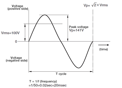
With AC input, input voltage is expressed using root-mean-square (RMS) value. The input voltage
defined in the standard specifications is regulated by the voltage between the power supply
input terminals.
With an AC power supply, there are two types of AC: single-phase AC and three-phase AC. The
differences between the two are shown in Fig. 1 and Fig. 2.
Generally, single-phase (100 V or 200 V) is used for low power supplies and three-phase (200 V)
is used for high power supplies.
Fig. 1 Single-phase AC
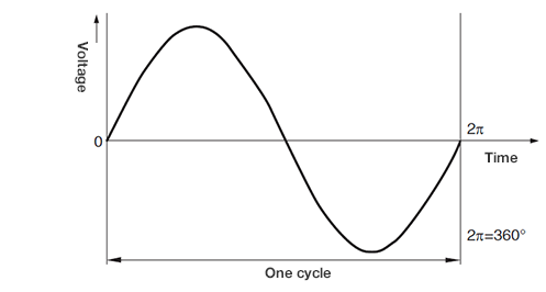
Fig. 2 Three-phase AC
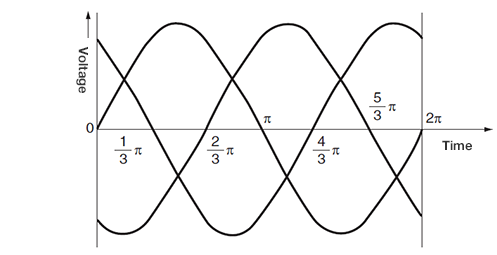
In three-phase systems, there are three equal electromotive forces of the same frequency with a
phase difference (time difference) of 120 degrees (2 π ÷ 3).
Compared to single-phase systems, the three-phase system in Fig. 2 has three electromotive
forces, and adjusting these can create a direct current voltage with low ripples.
Frequency range
Frequency range expresses the guaranteed frequency range of the AC input voltage shown on the specification sheet, and is expressed using the unit Hz.
AC85~265V
47Hz~63Hz(47Hz~440Hz)
Fig. 3 Voltage waveforms of commercial power supply (AC 100 V (50 Hz)
Power factor
Power factor is the ratio of working power to apparent power, and shows how effectively input power is being used. (Only power supply that conforms with high harmonic current regulations is noted in the standard specifications)
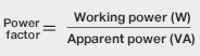
- Apparent power :
- Working power + Reactive power
- Working power :
- Power effectively consumed by the device
- Reactive power :
- Power from reactive current that returns to power supply without being consumed by the device
Efficiency
Efficiency is the ratio of output power to working input power, and is expressed using the unit %.
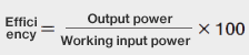
Fig. 4 Approach to efficiency
Notes
Current × Input voltage = Apparent power (VA)
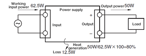
Input current
Input current is the current supplied to the power supply (expressed as root-mean-square (RMS) value) and is expressed using the unit A.

Notes
Input current and input voltage are root-mean-square values.
Fig. 5 Input voltage and peak current
In switched-mode power supplies, even if input voltage is a sinusoidal AC voltage, input current
will not always be a sinusoidal AC current.
As such, it’s important to note that input power does not equal control value × input current.
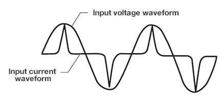
Input surge current (inrush current)
Input surge current is the maximum instantaneous current that flows into the smoothing capacitor
when power is input, and is expressed using the unit A. Input surge current is important
information when selecting switches and external fuses.
There are three types of input surge current prevention circuits: Power thermistor types,
thyristor types, and relay types.
Fig. 6 Inrush current
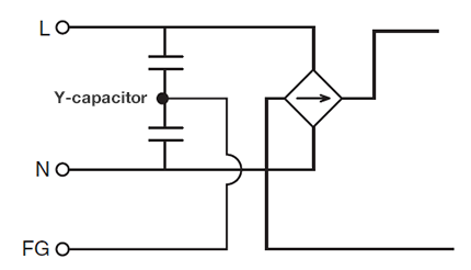
Leakage current
Leakage current is the current that passes from the input line through the housing and into the
ground, and is expressed using the unit mA. There are safety standards for leakage currents in
each country to prevent electric shocks and ensure safety in other ways.
Leakage current mainly refers to the current that flows into the ground (earth) from ground
capacitors (Y-capacitors) in input filter circuits. To reduce leakage current, users must reduce
the capacity of the Y-capacitor on the filter circuit. (Please note that noise attenuation
characteristics will change)
Fig. 7 Basic power supply input circuit diagram
Output
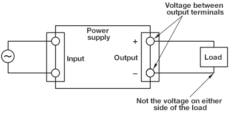
Rated voltage (rated direct current output voltage)
Rated voltage is the direct current voltage generated between power supply output terminals, and is expressed using the unit VDC.
Fig. 8 Correct output voltage measurement method
Maximum current (maximum direct output current)
Maximum current is the maximum output current that can be continuously supplied from the power supply, and is expressed using the unit A.
Average current lm (average output current)
The output current that can be continuously supplied from the power supply at peak load.
Maximum peak current lp (maximum peak output current)
The maximum output current that can be suppled within the regulated time from the power supply
at peak load.
Fig. 9 Output peak current calculation
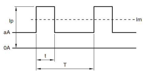
Iav≧Im=(Ip-a)×t/T+a
- lp:
- Peak current (A)
- lav:
- Average current (A) shown in catalog
- lm:
- Average current (A)
- t:
- Pulse width (seconds) of peak current
- T:
- Cycle (seconds)
Minimum current (minimum output current)
Minimum current is the minimum current required for stable operation of power supply. Minimum current is regulated for some products.
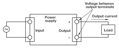
Maximum power (maximum output power)
Maximum power is the maximum output power that can be continuously supplied from the power supply, and is expressed using the unit W.

Fig. 10 Correct output voltage measurement method
Example:
Single output: 5 V × 20 A = 100 W
Triple output: (5 V × 3 A) + (12 V × 2 A) + (12 V × 1 A) = 51 W
Total maximum output power (multi output power supply only) is the sum of power from each output source that can be continuously supplied from the power supply.
Watt enclosure
If the total output power from each output CH is within the maximum total power on the technical
specifications, output current can be combined freely (the output current/power must not exceed
each CH).
Example: When using a triple output power supply
Total maximum output power ≧ CH1 output power + CH2 output power + CH3 output power
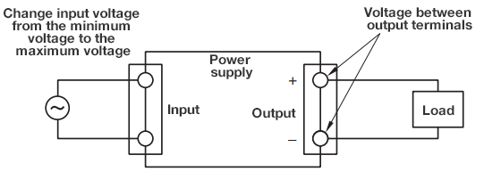
Maximum input fluctuation (static input fluctuation)
Maximum input fluctuation is the maximum output voltage fluctuation when input voltage is gently changed within the input voltage range, and is expressed using the unit mV or %.
Fig. 11 Correct output voltage measurement method
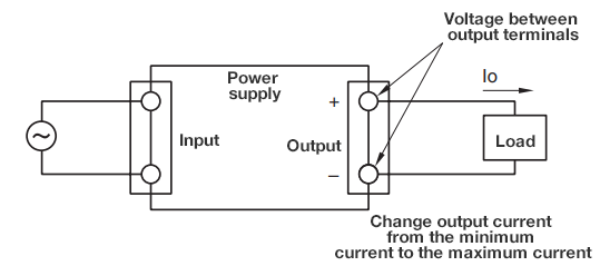
Maximum load fluctuation (static load fluctuation)
Maximum load fluctuation is the maximum output voltage fluctuation when output current is gently changed within the values shown on the standard specifications, and is expressed using the unit mV or %.
Fig. 12 Correct output voltage measurement method
Maximum temperature fluctuation
Maximum temperature fluctuation is the output voltage fluctuation when changing only the ambient temperature of the power supply. These figures allow the user to confirm whether output voltage is stable even when changing ambient temperature.
Example:
Products that show 0.02%/℃ mean that the output voltage changes at the rated value of 0.02% for
every 1℃.
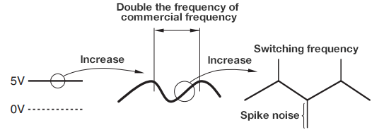
Ripple noise
Ripple noise is the maximum value of the minute AC voltage superimposed onto output voltage, and is expressed using the unit mVp-p.
Fig. 13 AC-DC power supply ripple noise
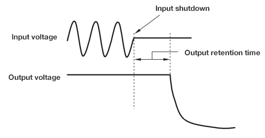
Retention time (output retention time)
Retention time is the time it takes for output voltage to start dropping (for voltage precision
to decrease) after shutting down power supply input, and is expressed using the unit ms.
During power outages and instantaneous power failures, users can use this time to protect
equipment operation, such as by saving computer memory.
Fig. 14 Output voltage retention time
Voltage variation range
Voltage variation range is the range within which output voltage can change, and is expressed using the unit VDC or %. Output voltage changing methods differ by product, and so it is important to check the handling instructions for each product.
Please note that with power supplies equipped with overvoltage protection circuits, turning up the output voltage adjustment volume too much (increasing the output voltage too much) can cause overvoltage protection to kick in and shut down the power supply. Further, when increasing output power supply, output current must be reduced to the value regulated in maximum output power.
Voltage setting precision
Voltage setting precision is the precision of the output voltage set at the time of shipment.
Functionality
Overcurrent protection (OCP)
Overcurrent protection is a function that controls output current to prevent it flowing above the specified value and at the same time prevents power supply breakdown by reducing output voltage, and is expressed using the unit % or A.
Values shown on the standard specifications show the range at which overcurrent protection kicks in (the output current at which output voltage starts to drop). Please note that continuous operation in an overcurrent state can lead to power supply breakdown (please refer to the handling instructions for each product).
Main characteristics of overcurrent protection
Overcurrent protection is a function that protects load and power supply when excess load
current flows due to load short circuits.
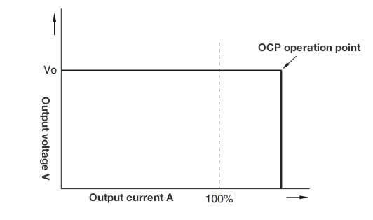
There are two main overcurrent protection types: constant current voltage drooping
characteristic types and foldback types.
Constant current voltage drooping characteristic type
When output current reaches the overcurrent detection value, the current is maintained while
reducing the voltage.
When output current falls below the overcurrent detection value, the output voltage
automatically returns. This is recommended when continuous operation is required.
Fig. 15 Constant current voltage drooping characteristic type
Foldback type
The shape of foldback overcurrent protection is shown in Fig. 16. Both output voltage and current fall when the overcurrent detection value is exceeded. With this method, as the output voltage does not automatically return, power must be reinput.
Fig. 16 Foldback type
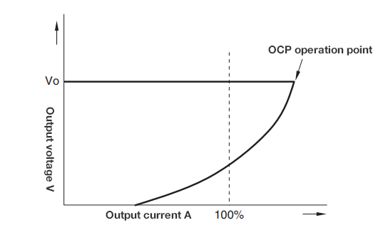
There are other products that allow for intermittent operation and output shutdown.
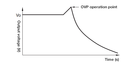
Overvoltage protection (OVP)
Overvoltage protection is a function that shuts down output when output voltage exceeds the
specified value and prevents the breakdown of loads connected to the output, and is expressed
using the unit % or VDC.
Values shown on the standard specifications show the range at which overvoltage protection kicks
in (the voltage at which output voltage starts is shut down).
Fig. 17 Overvoltage protection waveform
Output shutdown manual reset type
This type of overvoltage protection shuts down output when OVP kicks in. To return output, input voltage must temporarily be turned off, and power must be reinput after a certain amount of time. It is a model that can be reset by turning controls on and off.
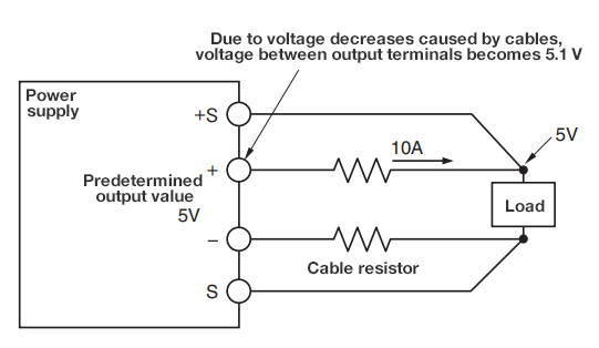
Remote sensing
Remote sensing is a function that corrects voltage drops caused by wiring resistors between the power supply output terminal and load.
Remote sensing is only possible with power supplies equipped with +S and -S terminals. +S and -S terminals detect output voltage, and predetermined output voltage is supplied to the points (sensing points) where the terminals connect.
Note: Correcting major line drops can cause the voltage between output terminals to rise, and may lead to output being shut down by OVP.
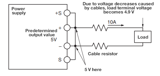
For systems that do not use remote sensing (local sensing systems), due to cable resistors, the voltage in load terminals will drop below the predetermined output voltage values.
Example:
With an output current of 10 A and a cable resistance of 0.01 Ω, voltage decreases caused by
cables will be 10 A × 0.01 Ω = 0.1 V, and load terminal voltage will be 5 V – 0.1 V = 4.9 V.
Fig. 18 Output voltage adjustment method (1)
Through remote sensing, the voltage of load terminals connected to +S and -S becomes the predetermined output voltage. The voltage between output terminals then exceeds the predetermined output voltage.
Example:
With an output current of 10 A and a cable resistance of 0.01 Ω, voltage decreases caused by
cables will be 10 A × 0.01 Ω = 0.1 V, and load terminal voltage will be 5 V + 0.1 V = 5.1 V.
Fig 19. Output voltage adjustment method (2)
Remote on/off control
Remote on/off control is a function that uses control signals to turn output on and off while power is still being input. Specifications differ depending on the product, and so it is important to check the handling instructions for each product.
Parallel operation
Parallel operation is when multiple power supply units are used to increase output
current.
In the case of a power supply breakdown, parallel operation is also used as a backup to maintain
voltage supply to the load through a reserve power supply. Specifications differ depending on
the product, and so it is important to check the handling instructions for each product.
Series operation
Series operation is when multiple power supply units are used to obtain the necessary voltage.
Instantaneous voltage drop protection
SEMI-F47
SEMI F47 is one standard for semiconductor processing equipment. SEMI F47 testing simulates when AC power supplies cause a sudden drop in voltage (several seconds from half a cycle) due to equipment failures or large load fluctuations in semiconductor factories, and assesses the durability of the equipment under test.
Fig. 20 Instantaneous voltage drop protection function
Environment
Operating temperature (operating ambient temperature)
Operating temperature is the ambient temperature range of a power supply that can guarantee continuous operation while fulfilling standard specifications, and is expressed using the unit ℃.
In some cases, due to ambient temperature, power supplies must be used while derating output power to ensure internal components do not exceed the rated temperature. Please note that the output derating curve may differ depending on the mounting method and presence or absence of a cover.
Storage temperature
Storage temperature is the ambient temperature range at which performance can be maintained even when the power supply is inactive, and is expressed using the unit ℃.
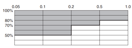
Operating humidity (operating ambient humidity)
Operating humidity is the relative humidity range of a power supply that can guarantee continuous operation while fulfilling standard specifications.
Storage humidity
Storage humidity is the relative humidity range at which electrical performance can be
maintained even when the power supply is inactive, and is expressed using the unit %RH.
Continuous storage in highly humid conditions can lead to rust and other issues and so should be
avoided.
Vibration resistance
Vibration resistance ensures power supplies will not breakdown in regulated testing conditions (JIS-C-60068-2-6 Sinusoidal vibration test method).
Example:
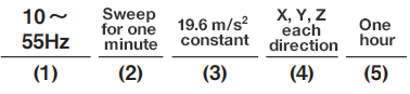
(1) Vibration frequency range: 10 to 55 Hz
(2) Time frequency is changed: 10 to 55 Hz and 55 to 10 Hz are changed each minute.
(3) Speed: Constant 19.6 m/s2.
(4) Vibration directions: Three directions X, Y, Z

(5) Testing time: One hour in each direction, total of three hours. The test is undertaken while the power supply is inactive. (9.8m/s2=1G)
Impact resistance
Impact resistance ensures power supplies will not breakdown in regulated testing conditions (IEC 60068-2-6 (2007) Impact test method). The test is undertaken while the power supply is inactive.
Cooling method
Cooling is a way to release the heat generated from the power supply.
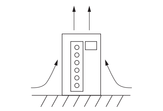
Natural air cooling
Heat release through natural convection
Fig. 21 Heat release through natural convection
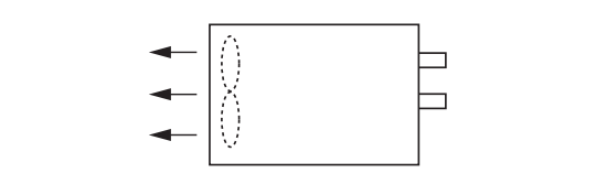
Forced air cooling
Heat release through use of a fan
Fig. 22 Heat release through use of a fan
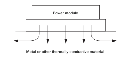
Conduction cooling
Heat release through thermal conduction
Fig. 23 Heat release through thermal conduction
Insulation
Withstand voltage
Withstand voltage is the applied voltage that can be withstood between specific terminals. Withstand voltage checks for insulation faults in primary-secondary circuits and primary-FG circuits.
Insulation resistance
Insulation resistance is the resistance value when a regulated direct current voltage is applied between specific terminals, and is expressed using the unit MΩ. Insulation resistance measures the resistance value of insulation material and confirms whether the insulation has degraded.
Reference: TDK Lambda material
Recommended Products
Switched-mode power supply
PDF list
Payment Method
- Credit Card
- PayPal
- Bank Transfer
Social Media
MISUMI Contact
Copyright © MISUMI Corporation All Rights Reserved.