(!)Due to
Microsoft's end of support for Internet Explorer 11 on 15/06/2022, this site does not support the recommended
environment.
Instead, please kindly use other browsers like Google Chrome, Microsoft Edge or Mozilla
Firefox.
- Please be informed that our operating hours on Hari Raya Puasa will be from 9:00 AM to 3:00 PM. Our office will be closed on 3 April 2026 in observance of the Good Friday holiday. More details.
- Notice of End of Sales for Economy Series Pneumatic Equipment Category. More details.
Crimp Terminal Basics
- The Relationship Between Cables, Crimp Terminals, and Crimp Tools
- Crimping Procedure
- Types of Crimp Tools
The Relationship Between Cables, Crimp Terminals, and Crimp Tools
(1) Select a terminal size that matches the cable size.
There are specific cable sizes with which general crimp terminals can be used.
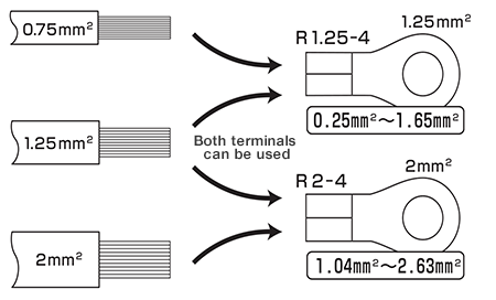
Important Point
Cables can come loose under the conjugation range and snap over the conjugation range and cause accidents.
(2) Select a crimp tool.
The type of crimp tool differs depending on the type of terminal. Please use the correct tool.
| Terminal | Correct tool |
|---|---|
|
Bare crimp terminal 
|
Bare terminal tool 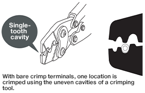
|
|
Insulated crimp terminal 
|
Insulated terminal tool 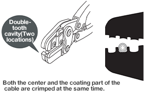
|
|
Closed end connection terminal 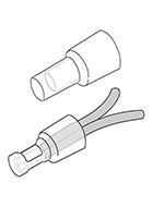
|
Closed end connection terminal tool 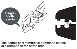
|
Common Accidents
Crimping an insulated terminal using a covered crimp terminal tool. The insulator tore, exposed the metal part of the terminal, and caused a short circuit.

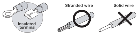
FAQ: Is it possible to simply use the insulated terminal sleeve?
Use a bare crimp terminal/bare crimp sleeve with a solid wire, and insulate using an
insulation cap, insulation tube, or insulation taping, etc.
Common Accidents 1
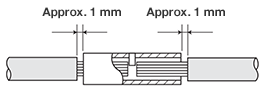
See below for connections using closed end connection terminals. (Note: JIS C 2807:2003)

- 1. When crimping cables, ensure that the maximum wire diameter of both solid wires and stranded wires is 1 mm.
- 2. When crimping and connecting cables with different wire diameters, if the diameter of the wider cable exceeds 0.5 mm, in principle, the width of the narrower cable should be more than half the diameter of the wider cable.
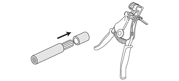
Crimping Procedure
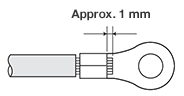
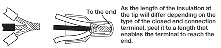
(1) Peel back the cable coating.
Following the user instructions for each type of terminal, peel back the coating on the cable terminal. The size of the coating will differ depending on the style and shape of the terminal.
| Bare crimp terminal |
|
| Bare crimp P sleeve |

|
| Bare crimp B sleeve |
|
| Ring sleeve |
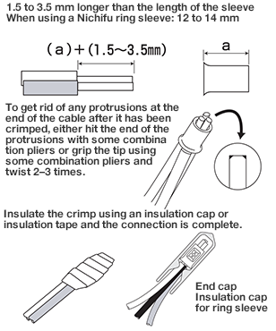
|
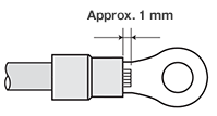
| Closed end connection terminal |
|
| Insulated terminal |
|
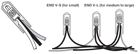
End Cap (Insulation Cap for Ring Sleeve)
- Simply cover the ring sleeve with an end cap for insulation.
- Semi-transparent types enable users to confirm the quality of connection.
- Outstanding safety (insulation performance).
- A flexible cap that conforms with the revised RoHS Directive (four phthalic acid substances).
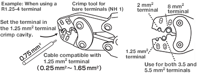
(2) Crimp
The cavities used to crimp are specified for each terminal size.
| 1. Determine the cavity used to crimp |
|
| 2. With the silver solder at the top, crimp the terminal using the male die. |

|
| 3. Temporarily place the terminal in the cavity and insert the cable. |

|
| 4. Grip until the ratchet is released. |
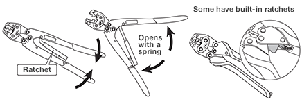
Do not remove the ratchet from the crimp tool. |
Important Point Crimping Insulated Terminals
Crimping cavities can crimp both the center and the coating part of the cable at the same time. Please ensure the terminal is facing the right direction.
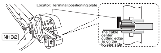
*Remove this locator when crimping terminals that are not round or open-ended style, such as insulated sleeves.
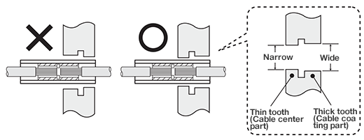
Important Point Crimping direction
The height and width of the two cavities are different, and so placing the terminal or sleeve in the wrong direction can lead to insufficient crimping of the cable, and in turn cause the cable to come loose.
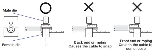
Important Point Correct Crimp Position
Crimp the center of the pipe (where cable is inserted).
| Covered crimp terminal/sleeve | ||
|---|---|---|
|
Crimp cross-section 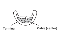
|
P sleeve (overlapping) 
|
B sleeve (placed opposite) 
|
| Insulated terminal/sleeve | ||
|---|---|---|
|
Crimp cross-section 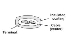
|
Insulated crimp terminal 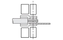
|
Insulated B sleeve 
|
(3) Post-crimping Visual Testing
| Bare crimp terminal | Insulated coating crimp terminal | Decision |
|---|---|---|

|

|

|

|

|

|

|

|

|

|

|

|

|

|

|
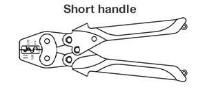
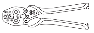
Types of Crimp Tools
For bare crimp terminals and sleeves
・NH1 395g/235mm
(Compatible terminal size: 1.25 to 8 mm2)

・NH69 250g/180mm
(Compatible terminal size: 0.3/0.5 to 2 mm2)
For ring sleeves
・NHE4 410g/240mm
(Compatible terminal size: E small/medium/large)
For insulated crimp terminals and sleeves
・NH32 450g/241mm
(Compatible terminal size: 0.3/0.5 to 2 mm2)

Closed end connection terminal
・NH38 430g/250mm
(Compatible terminal size: CE1/CE2/CE5/CE8)

*Please note that tool models are subject to remodel.
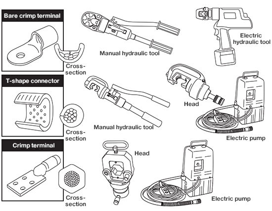
Large crimp terminals/Crimp terminals/T-shape connectors
Crimping of large terminals is undertaken using manual hydraulic tools, electric hydraulic tools, or crimp heads and hydraulic pumps.
Useful Info:Discovery and the History of Cable Connections
Initially, when connecting cables in internal wiring systems, the method used in each country
was simply to connect the cables directly. Later, the cables were soldered and reinforced, and
this method came to be widely used. From around 1925, a new method that didn’t rely on soldering
was developed in Europe and the US, and gradually came to be used in other countries.
After World War II, the crimping connection method proliferated at a rapid pace, and today we
rarely see the soldering method at all.
| 1835 | Samuel Morse of the US invented the wired electrical telegraph. It was from around this time that large numbers of cables came to be connected. |
| 1858 | XXX Duboscq of France invented the world’s first practical arc lamp. |
| 1876 | Alexander Graham Bell of the US invented the telephone. |
| 1879 | Thomas Edison of the US invented the incandescent light bulb. |
| 1882 | The world’s first power distribution system was launched in New York. |
| 1887 | Japan’s first power distribution system was launched in Tokyo. |
It was from around this time that cable connection work began on Japan’s internal wiring systems and power distribution lines.
Reference: Nichifu material
Recommended Products
Crimp terminal

NICHIFU TERMINAL INDUSTRIES


NICHIFU TERMINAL INDUSTRIES

Crimp tools/IDC tools


PDF list
Payment Method
- Credit Card
- PayPal
- Bank Transfer
Social Media
MISUMI Contact
Copyright © MISUMI Corporation All Rights Reserved.