PLC SYSMAC CJ Series CJ2H
Caution
Product Description
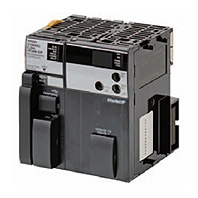
- PLC SYSMAC CJ series CPU unit by OMRON.
- High-speed, high-capacity EtherNet/IP is built into every model.
- The CIP communications protocol is supported for direct access to multi-manufacture devices.
- Tag memory provided for easy access from host PCs and PTs.
- Even more program memory and data memory.
- Superior high-speed control performance.
- The more advanced motion control by the lower cost (Synchronous Unit Operation).
- Increased I/O throughput speed by [Direct processing of every refreshing command].
CJ Series CJ2H CPU Unit CJ2H-CPU6□(-EIP) Specifications of OMRON PLC

PLC Appearance of CJ2H-CPU6□

PLC CJ2H-CPU6□ dimensional diagram (unit: mm)

PLC Appearance of CJ2H-CPU6□-EIP

PLC CJ2H-CPU6□-EIP dimensional drawing (unit: mm)
| PLC Model | CJ2H | ||
|---|---|---|---|
| type | High-end type | Flagship Type | |
| format | Model CJ2H-CPU6□ | Model CJ2H-CPU6□-EIP | |
| Program Capacity | Up to 400K steps | ||
| Data Memory Capacity | Up to 832K words | ||
| Input/Output Points | 2,560 points | ||
| Basic instruction execution speed(LD) | 16ns | ||
| Application instruction execution speed(MOV) | 48ns | ||
| Floating-point operation(SIN) | 0.59μs | ||
| Common Processing Time | 100μs | 200μs | |
| Communication Port | USB port | ○ | |
| Serial Port | ○ (RS-232C) | ||
| EtherNet/IP port | - | ○ | |
| Interrupt high-speed startup function | ○ | ||
| Inter-unit synchronous control function | Yes (When combined with Position Control Unit CJ1W-NC□□4) | ||
Specification Table of OMRON PLC
| PLC item | format | |||||
|---|---|---|---|---|---|---|
| Model CJ2H- | ||||||
| CPU64(-EIP) | CPU65(-EIP) | CPU66(-EIP) | CPU67(-EIP) | CPU68(-EIP) | ||
| structure | Built-in type | |||||
| Grounding Method | D class grounding (3rd class grounding) | |||||
| External dimensions (height x depth x width) | Model CJ2H-CPU6□-EIP: 90mm x 65mm x 80mm Model CJ2H-CPU6□: 90mm x 65mm x 49mm | |||||
| Mass * | Model CJ2H-CPU6□-EIP: 280g or less Model CJ2H-CPU6□: 190g or less | |||||
| Current consumption | Model CJ2H-CPU6□-EIP: DC5V 0.82A Model CJ2H-CPU6□: DC5V 0.42A | |||||
| Operating environment | Ambient temperature | 0 to 55°C | ||||
| Ambient humidity | 10 to 90% RH (no condensation) | |||||
| Ambient environment for use | No corrosive gases | |||||
| Storage ambient temperature | -20 to +70°C (excluding battery) | |||||
| Use altitude | Under 2,000m | |||||
| Pollution level | Pollution level 2 or less: Corresponding to IEC61010-2-201 | |||||
| Noise resistance | Compliant with IEC61000-4-4 2kV (power line) | |||||
| Overvoltage Category | Category II: Corresponding to IEC61010-2-201 | |||||
| EMC Immunity Level | Zone B | |||||
| Vibration resistance | Compliant with JIS C60068-2-6 5 to 8.4 Hz, amplitude 3.5 mm, 8.4 to 150 Hz, acceleration 9.8 m/s2, 100 minutesineach of the X, Y, and Z directions (sweep time 10 minutes x number of sweeps 10 times = total 100 minutes) | |||||
| Shock Resistant | Compliant with JIS C60068-2-27: 147m/s2,3 times each in X, Y, and Z directions (100m/s2 for relay outputunit) | |||||
| Battery | lifespan | 5 years 25℃ | ||||
| mass | Approximately 10g | |||||
| Usage format | Model CJ1W-BAT01 | |||||
| Compliance standards | Compliant with CULUS, NK, LR, and EC directives | |||||
* Includes the weight of the end cover and battery.
Specification Table of OMRON PLC
| PLC item | format | ||||||
|---|---|---|---|---|---|---|---|
| Model CJ2H- | |||||||
| CPU64(-EIP) | CPU65(-EIP) | CPU66(-EIP) | CPU67(-EIP) | CPU68(-EIP) | |||
| Program Capacity | 50K steps | 100K steps | 150K steps | 250K steps | 400K steps | ||
| Input/Output Points | 2560 points | ||||||
| Processing speed | Common processing time (overhead) *1 | Normal mode: CJ2H-CPU6□-EIP: 200 μs CJ2H-CPU6□: 100 μs | |||||
| Instruction Execution Time | Basic commands: 0.016μs and up Application commands: 0.048μs and up | ||||||
| Barge | I/O interrupts and external interrupts | Interrupt task start time: 26μs or 17μs *2 (30μs for unit version 1.0) Return time to cyclic task: 11μs or 8μs *2 (15μs for unit version 1.0) | |||||
| Regular interrupt | Minimum time interval: 0.2ms or 0.1ms *2 (set in 0.1ms increments) | ||||||
| Interrupt task start time: 22μs or 13μs *2 (27μs for unit version 1.0) Return time to cyclic task: 11μs or 8μs *2 (15μs for unit version 1.0) | |||||||
| Number of units that can be connected | - | 10 units per device (CPU or expansion). 40 units in the basic system | |||||
| Basic I/O unit | No limit , but up to 2 interrupt input units (CJ1W-INT01) are allowed | ||||||
| High-performance I/O unit | Up to 96 units (unit numbers 0 to 95) can be installed (depending on the model, units 1 to 8 may be occupied) | ||||||
| CPU high-performance unit | Model CJ2H-CPU6□-EIP: Maximum 15 Trapezoidal CJ2H-CPU6□: Maximum 16 units | ||||||
| Where interrupt functions can be used | CJ2H-CPU6□-EIP: CPU device slots 0 to 3CJ2H-CPU6□: CPU device slots 0 to 4 | ||||||
| Number of additional racks | Up to 3 | ||||||
| CIO | Input/Output Relays | 2560 points (160CH) 0000~0159CH | |||||
| Data Link Relay | 3200 points (200CH) 1000~1199CH | ||||||
| Synchronous Data Link Relay | 1536 points (95CH) 1200-1295CH | ||||||
| CPU High Function Unit Relay | 6400 points (400CH) 1500~1899CH | ||||||
| High-performance I/O unit relay | 15360 points (960CH) 2000-2959CH | ||||||
| DeviceNet Relay | 9600 points (600CH) 3200~3799CH | ||||||
| Internal Auxiliary Relay | Channel I/O (CIO) Area | 3200 points (200 words) 1300 to 1499 words, 37504 points (2344 words) 3800 to 6143 words External input/output is not possible | |||||
| W Relay | 8192 points (512CH) W000 to W511CH External input/output is not possible | ||||||
| Holding Relay | 8192 points (512CH) H000 to H511CH can only be used in programs, and ON/OFF is maintained even when power is restored or the mode is changed. H512 to H1535 are relays dedicated to function blocks (they can only be set in the FB instance area (internal allocation range of variables).) | ||||||
- *1. When using the EtherNet/IP tag data link of the CJ2H-CPU6□-EIP, the following is added: Normal: 100 μs + number of channels transferred × 0.33 μs When using the interrupt high-speed start function: 100 μs + number of channelstransferred × 0.87 μs
- *2. When using the interrupt high-speed startup function.
| PLC item | format | |||||
|---|---|---|---|---|---|---|
| Model CJ2H- | ||||||
| CPU64(-EIP) | CPU65(-EIP) | CPU66(-EIP) | CPU67(-EIP) | CPU68(-EIP) | ||
| Special Auxiliary Relay | Readable/Writable: 31744 points (1984CH) / 7168 points (448CH) A000 to A447CH / 24576 points (1536CH) A10000 to A11535CH *1 Readable / Writable: 16384 points (1024CH) A448 to A1471CH *1 | |||||
| Temporary Memory Relay | 16 points TR0-15 | |||||
| Timer | 4096 points T0000 to T4095 (separate from counter) | |||||
| counter | 4096 points C0000 to C4095 (separate from timer) | |||||
| Data Memory | 32K words *2 ・DM area for high-performance I/O unit: D20000 to D29599 (100CH x 96 units) ・DM area for high-performance CPU unit: D30000 to D31599 (100CH x 16 units) | |||||
| Expanded Data Memory | 32K words/1 bank x 1 to max. 25 banks: E00_00000 to max. E18_32767 *2, *3 | |||||
| 32K words x 4 banks | 32K words x 4 banks | 32K words x 10 banks | 32K words x 15 banks | 32K words x 25 banks | ||
| Forced set/reset possible area *4 | When using the EM forced set/reset function | Bank 0 to 3 | Bank 0 to 3 | Bank 0 to 9 | Bank 0 to E | Bank 0 to 18 |
| When automatic address allocation is specified | Bank 3 | Bank 3 | Banks 6 to 9 | Bank 7 to E | Bank 11 to 18 | |
| Index Register | IR0 to IR15 registers: Dedicated registers that store I/O memory effective addresses for indirect reference (selectable between independent for each task and shared among tasks) | |||||
| Cyclic execution task flag | 128 points | |||||
| Memory Card | 128MB, 256MB, 512MB | |||||
| Operational Mode | "Program mode": The program is stopped. This mode is used for preparation before execution. "Monitor mode": The program is running. Operations such as online editing and changing the current values of I/O memory are possible. "Operation mode": The program is running. This mode is used during normal operation. | |||||
| Execution Mode | Normal Mode | |||||
| Programming description language | Ladder Logic (LD), Sequential Function Chart (SFC), Structured Text (ST), Instruction List (IL) | |||||
| Function Blocks | Define maximum number | 2048 | ||||
| Maximum Number of Instances | 2048 | |||||
| task | Task Type | Cyclic execution tasks, interrupt tasks (power-off interrupt tasks, scheduled interrupt tasks, I/O interrupt tasks, external interrupt tasks) | ||||
| Number of tasks | Cyclic tasks: 128 Interrupt tasks: 256 (384 tasks can be used as cyclic tasks if interrupt tasks are used as additional tasks) | |||||
- *1 . A960 to A1471CH and A10000 to A11535CH cannot be accessed from CPU special units, special I/O units, displays, software, etc. that are not compatible with CJ2 CPU units.
- *2 Bit addressing is possible. However, bit access is not possible from CPU special units, special I/O units, displays, software, etc. that are not compatible with the CJ2 CPU Unit.
- *3 EM banks D to 18 cannot be accessed from CPU special units, special I/O units, displays, software, and other devices that are not compatible with the CJ2 CPU Unit.
- *4 . For CJ2H CPU Units, only the areas specified for automatic address allocation or the areas specified by the EM force set/reset function can be force set/reset (Unit version 1.2 or later).
*Only some product information is listed.