(!)Due to Microsoft's end of support for Internet Explorer 11 on 15/06/2022, this site does not support the recommended environment.
Instead, please kindly use other browsers like Google Chrome, Microsoft Edge or Mozilla Firefox.
50,000 Stock items for Same Day Ship Out.
All Categories
Categories
- Automation Components
A wide variety of standard and configurable components for factory automation engineers in industries such as automotive, semiconductor, packaging, medical and many more.
- Linear Motion
- Rotary Motion
- Connecting Parts
- Rotary Power Transmission
- Motors
- Conveyors & Material Handling
- Locating, Positioning, Jigs & Fixtures
- Inspection
- Sensors, Switches
- Pneumatics, Hydraulics
- Vacuum Components
- Hydraulic Equipment
- Discharging / Painting Devices
- Pipe, Tubes, Hoses & Fittings
- Modules, Units
- Heaters, Temperature Control
- Framing & Support
- Casters, Leveling Mounts, Posts
- Doors, Cabinet Hardware
- Springs, Shock Absorbers
- Adjusting, Fastening, Magnets
- Antivibration, Soundproofing Materials, Safety Products
- Fasteners
A good selection of accessories such as screws, bolts, washers and nuts that you may need for your daily engineering usage.
- Materials
Browse industrial materials ranging from heat insulating plates, sponges, to metal and plastic materials in different sizes to meet your various applications.
- Wiring Components
A wide variety of wiring parts for connecting and protecting control and PC parts including Connectors, Cables, Electric Wires, Crimping Terminals and more.
- LAN Cables / Industrial Network Cables
- Cables by Application
- Cables with Connectors
- RS232 / Personal Computers / AV Cables
- Wires/Cables
- Connectors (General Purpose)
- Crimp Terminals
- Zip Ties
- Cable Glands
- Cable Bushings/Clips/Stickers
- Screws/Spacers
- Cable Accessories
- Tubes
- Protection Tubes
- Ducts/Wiremolds
- General Purpose Tools
- Dedicated Tools
- Soldering Supplies
- Electrical & Controls
A wide variety of controls and PC parts for electrical engineers including Controls, Powers, PC parts and more.
- Cutting Tools
A wide variety of cutting tools for many uses and work materials including End Mills, Drills, Cutters, Reamers, Turning Tools and more.
- Carbide End Mills
- HSS End Mills
- Milling Cutter Inserts/Holders
- Customized Straight Blade End Mills
- Dedicated Cutters
- Turning Tools
- Drill Bits
- Screw-Hole-Related Tools
- Reamers
- Chamfering / Centering Tools
- Fixtures Related to Cutting Tools
- Step Drills
- Hole Saws
- Clean Key Cutters
- Core Drills (Tip Tools)
- Magnetic Drilling Machine Cutters
- Drill Bits for Electric Drilling Machines
- Woodworking Drill Cutters
- Drills for Concrete
- Processing Tools
A wide variety of tools and supplies used in processing including Machine Tools, Measurement Tools, Grinding and Polishing Supplies and more.
- Material Handling & Storage
A wide variety of goods used in shipment, material handling and warehouse including Tape supplies, Stretch film, Truck, Shelf, Crane and more.
- Tape Supplies
- Cushioning Materials
- Stretch Films
- Cardboard
- Plastic Bags
- PP Bands
- Magic Tapes / Tying Belts
- Rubber Bands
- Strings/Ropes
- Cable Ties
- Tags
- Labelers
- Unpacking Cutters
- Packing Support Equipment
- Cloth Sheets for Packing
- Conveyance/Dolly Carts
- Tool Wagons
- Tool Cabinets / Container Racks
- Lifters / Hand Pallets
- Container Pallets
- Storage Supplies
- Shelves/Racks
- Work Benches
- Suspended Clamps/Suspended Belts
- Jack Winches
- Chain Block Cranes
- Bottles/Containers
- Bicycle Storage Area
- Safety & General Supplies
A large variety of goods for every kind of factories and offices including Protection items, Cleaning supplies, sanitations, office supplies and more.
- Lab & Clean Room Supplies
A large variety of items used in R&D and Clean Room including research Equipment, Laboratory Essentials, Analysis Supplies, Clean Environment-Related Equipment and more.
- Press Die Components
Choose from thousands of standard stamping die components including Punch & Die, Gas Springs, Guide Components, Coil Springs and many more.
- Plastic Mold Components
Browse our wide variety of mold components including Ejector Pins, Sleeves, Leader Components, Sprue Bushings and many more.
- Ejector Pins
- Sleeves, Center Pins
- Core Pins
- Sprue bushings, Gates, and other components
- Date Mark Inserts, Recycle Mark Inserts, Pins with Gas Vent
- Undercut, Plates
- Leader Components, Components for Ejector Space
- Mold Opening Controllers
- Cooling or Heating Components
- Accessories, Others
- Components of Large Mold, Die Casting
- Injection Molding Components
Browse our injection molding components including Heating Items, Couplers, Hoses and more.
- Injection Molding Machine Products
- Accessories of Equipment
- Auxiliary Equipment
- Air Nippers
- Air Cylinders
- Air Chuck for Runner
- Chuck Board Components
- Frames
- Suction Components
- Parallel Air Chuck
- Special Air Chuck
- Chemical for Injection Molding
- Mold Maintenance
- Heating Items
- Heat Insulation Sheets
- Couplers, Plugs, One-touch Joints
- Tubes, Hoses, Peripheral Components
Search by Application
Brands


- Scheduled Maintenance Notice: This site will be unavailable due to scheduled maintenance from 9:00 21/4/2024 to 6:00 (SGT) 22/4/2024. We apologize for the inconvenience.
- Please Note our New Address (effective April 1, 2024): 331 North Bridge Rd, #05-01 Odeon 331, Singapore 188720.
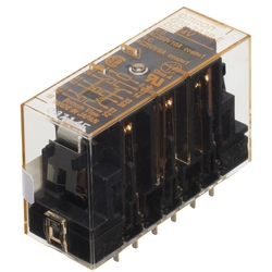
Safety Relay, G7S
[Features]
· Safety rail for safety light curtain F3SJ-E. G7S.
Japanese Only
Part Number
Configured Part Number is shown.
Safety Relay G7S Series Specifications
| Classification | Number Of Poles | Contact Configuration | Rated Voltage | Format |
|---|---|---|---|---|
| Standard Type | 6 poles | 4 a 2 b | 24 V DC | Model G7S-4A2B-E |
| 3 a 3 b | Model G7S-3A3B-E |
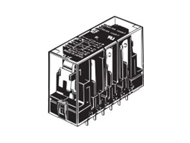
G7S-4A2B-E/G7S-3A3B-E external appearance
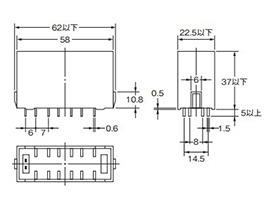
G7S-4A2B-E/G7S-3A3B-E dimensional drawings, Units: mm
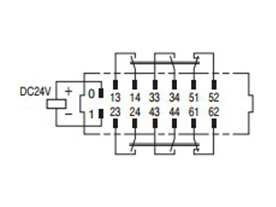
G7S-4A2B-E terminal layout / internal schematics
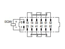
G7S-3A3B-E terminal layout / internal schematics
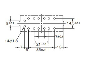
Mounting hole dimensions, Units: mm
Rating
Operating Coil
| Rated Voltage | Rated Current (mA) | Coil Resistance (Ω) | Maximum Continuous Allowable Voltage (V) | Power Consumption (W) |
|---|---|---|---|---|
| 24 V DC | 30 | 800 | 110% | Approx. 0.8 |
- *The rated current and coil resistance are measured at a coil temperature of 23°C with tolerances of ±15%.
- *The figures for the operating characteristics are for a coil temperature of +23°C.
Switch (Contact)
| Load | Resistive Load | |
|---|---|---|
| Rated Load | a-Contact | 250 V AC 10 A, 30 V DC 10 A |
| b Contact | 250 V AC 6 A, 30 V DC 6 A | |
| Rated Carry Current | a-Contact | 10 A |
| b Contact | 6 A | |
| Max. Contact Voltage Value | 250 V AC, 30 V DC | |
| Max. Contact Current Value | a-Contact | 10 A |
| b Contact | 6 A | |
| Contact Resistance *1 | 100 mΩ max. | |
|---|---|---|
| Operating Time *2 | 50 ms max. | |
| Recovery Time *2 | 50 ms max. | |
| Operating Voltage | 80% max. relative to rated voltage | |
| Release Voltage | 10% min. relative to rated voltage | |
| Maximum Switching Frequency | Mechanical | 18,000 operations/hr |
| Rated Load | 1,800 operations/hr | |
| Insulation Resistance *3 | 100 MΩ min. | |
| Dielectric Strength *4 *5 | Between coil and contacts (between coil and pole 3 or coil and pole 4): 4,000 VAC, 50/60 Hz for 1 min Between coil and contacts (other than the above): 2,500 VAC, 50/60 Hz for 1 min Between different poles (between pole 1, 3, or 5 and pole 2, 4, or 6): 4,000 VAC, 50/60 Hz for 1 min Between different poles (other than the above): 2,500 VAC, 50/60 Hz for 1 min Between contacts of same polarity: 1,500 VAC, 50/60 Hz for 1 min | |
| Vibration | Durability | 10 to 55 to 10 Hz, 0.75-mm single amplitude (1.5-mm double amplitude) |
| Malfunction | 10 to 55 to 10 Hz, 0.375-mm single amplitude (0.75-mm double amplitude) | |
| Shock | Durability | 1,000 m/s2 |
| Malfunction | 100 m/s2 | |
| Durability *6 | Mechanical | 10,000,000 operations min. (switching frequency 18,000 operations/hr) |
| Electrical | 100,000 operations min. (at 1,800 operations/hr under rated load) | |
| Inductive Load Switching Performance *7 (IEC60947-5-1) | a-Contact | AC15 240 V AC 5 A DC13 24 V DC 2 A |
| b Contact | AC15 240 V AC 3 A DC13 24 V DC 2 A | |
| Failure Rate (P Level) (Reference Value *8) | 5 V DC 1 mA | |
| Ambient Operating Temperature | -25 to +70°C (assuming no icing or condensation) | |
| Ambient Operating Humidity | 5 to 85% RH | |
| Weight | Approx. 65 g | |
- The values given above are initial values.
- *The figures for the operating characteristics are for a coil temperature of +23°C.
*1. Measurement conditions: 5 V DC, 10 mA, voltage drop method.
*2. Measurement conditions: rated voltage operation. Ambient temperature conditions: +23°C. Bounce time not included.
*3. Measured with a 500 V DC ohmmeter at the same places that the dielectric strength was checked.
*4. When using a P7S socket, the dielectric strength between coil contacts/different poles is 2,000 V AC, 50/60 Hz for 1 min.
*5. The coil refers to terminals 0-1, pole 1 refers to terminals 13−14, pole 2 refers to terminals 23−24, pole 3 refers to terminals 33−34, pole 4 refers to terminals 41−42 or 43−44, pole 5 refers to terminals 51−52, and pole 6 refers to terminals 61−62.
*6. The durability is for an ambient temperature of 15 to +35°C and an ambient humidity of 25% to 75% RH.
*7. AC15: cosφ = 0.3 mm, DC13: L/R = 96 ms inductive load.
*8. This value is based on a switching frequency of 60 operations/min.
- *See the catalog for usage precautions, etc.
| Part Number |
|---|
| G7S-3A3B-E DC24 |
| G7S-4A2B-E DC24 |
| Part Number | Standard Unit Price | Minimum order quantity | Volume Discount | Days to Ship | Contact Configuration |
|---|---|---|---|---|---|
SGD 54.18 | 1 Piece(s) | 4 Day(s) or more | [Other] 3a3b | ||
SGD 54.18 | 1 Piece(s) | Same day | [Other] 4a2b |
Loading...
Basic Information
| Application | Safety relay | Latch function | NA | Terminal shape | Socket / plug-in |
|---|---|---|---|---|---|
| Contact rated current (minimum value for AC and DC)(A) | 6 | Coil rated voltage (DC)(V) | 24 | Representative Standard | UL / CSA |
| Dimension height(mm) | 37 | Dimension width(mm) | 22.5 | Dimension depth(mm) | 58 |
| Classification | Standard Type | Note | Dangerous situations in and around the machinery are avoided by the use of an interlock type circuit configuration. |
- The specifications and dimensions of some parts may not be fully covered. For exact details, refer to manufacturer catalogs .
Tech Support
- Factory Automation, Electronics, Tools, & MRO (Maintenance, Repair and Operations)
- Tel:(65) 6733 7211 / FAX:(65) 6733 0211
- 9:00am - 6:00pm (Monday - Friday)
- Technical Inquiry
Payment Method
- Credit Card
- PayPal
- Bank Transfer
Social Media
MISUMI Contact
Copyright © MISUMI Corporation All Rights Reserved.
How can we improve?
How can we improve?