Miniature Low-Profile Interface DN Connector
Caution
Product Description
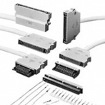
This small, multi-pin rectangular connector was developed to support the miniaturization of electronic devices, and thinner devices in particular
[Features]
· The terminal's wire connector is arrayed in a 2.54 mm grid that makes it easy to design circuits on a printed circuit board.
· The structure of the terminal is based on the manufacturer's SM series (D-sub connectors). This gives the terminal dependable quality.
· The single-action lock mechanism provides excellent operability.
· The cover case is designed to be thin and compact and features a low profile in order to meet the needs of high-density mounting. Mounting with 17.78 mm (700 mils) between circuit boards is possible.
· The cover case is made of an aluminum die casting offering good electromagnetic shielding characteristics. Combined with the connector's metal shell, the above configuration ensures that noise is reduced.
· The dip connector includes a snap (circuit board temporary joint) bracket.
· Pressure Connecting type supports connection of two wire types, AWG 26 and 28, via pressure welding, for use with standard 1.27-mm pitch cables.
· Crimping type can be used to perform crimping of AWG 26 to 28 wiring.
· Depending on the application, cable can be extracted in either the vertical or horizontal direction.
Rectangular (2.54 Grid D Type) Miniature Low-Profile Interface Connector

DN Series
Specifications of Miniature Low-Profile Interface DN Connector
| Item | Standard Value |
|---|---|
| Operating Temperature Range | -55 to +85°C |
| Current Capacity | 3 A |
| Rated voltage | 200 V AC |
| Insulation resistance | 5,000 MΩ or more at 500 V DC |
| Contact resistance | 20 mΩ or less at 100 mA DC |
| Withstand Voltage | 1,000 V AC for 1 minute |
Product Standards
| Part Name | Materials | Color/Finish |
|---|---|---|
| Plug case | Aluminum alloy die-cast | Silver coating |
| Insulator | PBT resin* | Black |
| Contacts | Copper alloy | Nickel plating + Selective gold plating |
Materials/Processing
- *UL94V-0
Product Outline Drawing And Dimensions
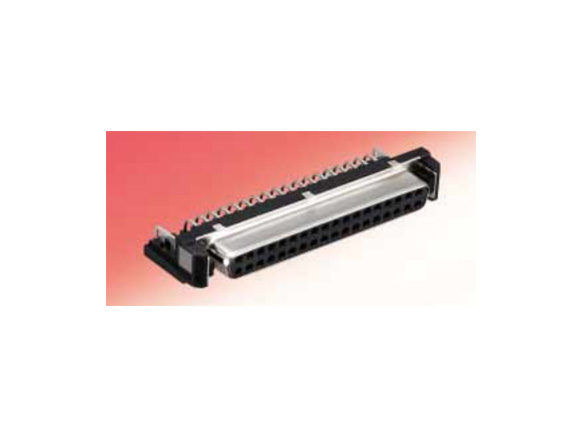
DN10-36S(50)
right-angle DIP female connector
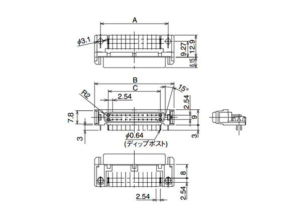
Right-angle DIP female connector dimensional drawing
Units: mm
| Product No. | HRS No. | Number of Contacts | A | B | C |
|---|---|---|---|---|---|
| DN10-20S(50) | 225-0015-0 50 | 20 | 32 | 38.9 | 22.86 |
| DN10-36S(50) | 225-0002-9 50 | 36 | 52.3 | 59.2 | 43.18 |
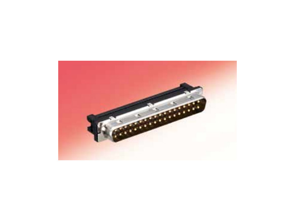
DN30-36P(50)
male ID connector
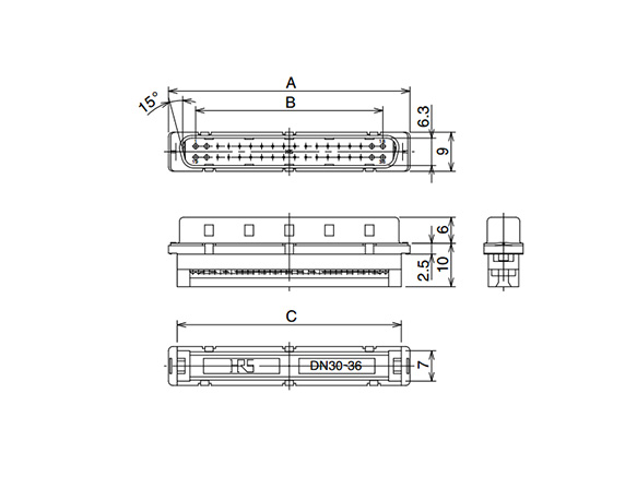
Male ID connector dimensional drawing
Units: mm
| Product No. | HRS No. | Number of Contacts | A | B | C |
|---|---|---|---|---|---|
| DN30-36P(50) | 225-0027-0 50 | 36 | 55.68 | 49.4 | 51.7 |
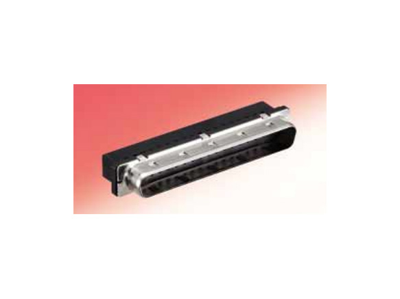
DN50-36P
male crimp connector
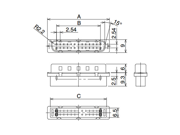
Male crimp connector dimensional drawing
Units: mm
| Product No. | HRS No. | Number of Contacts | A | B | C |
|---|---|---|---|---|---|
| DN50-26P | 225-0004-4 | 26 | 42.98 | 30.48 | 39 |
| DN50-50P | 225-0006-0 | 50 | 73.46 | 60.96 | 69.48 |
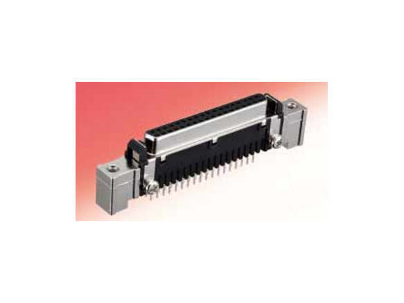
DN20B-36S(50)
straight DIP female connector
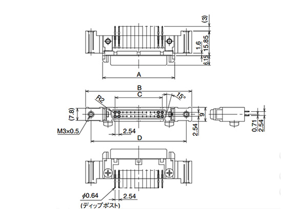
Straight DIP female connector dimensional drawing
Units: mm
| Product No. | HRS No. | Number of Contacts | A | B | C | D |
|---|---|---|---|---|---|---|
| DN20B-36S(50) | 225-0047-7 50 | 36 | 59.2 | 81.2 | 43.18 | 74.2 |
PCB Reference Dimensional Drawing

PCB Reference Dimensional Drawing
Panel Reference Dimensional Drawing
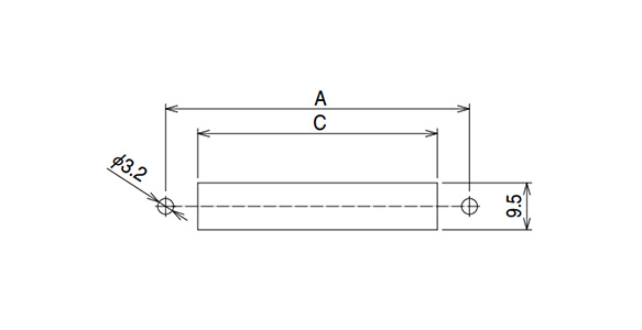
Panel Reference Dimensional Drawing
Units: mm
| Number of Contacts | A | B | C |
|---|---|---|---|
| 20 | 53.9 | 9 | 40.9 |
| 36 | 74.2 | 17 | 61.2 |
| 50 | 92 | 24 | 79 |
Dimensions for panel reference dimensional drawing
- 1. Use a panel with a thickness of 1.6 mm.
- 2. The board reference diagram shows the connector-mounting surface. The areas marked with [ ] is to be prohibited from entering any pattern.
- 3. The circuit board and panel are related to each other, with a ø3.2 mm mounting hole as the reference point.
- 4. Use a panel with a thickness of 1.6 mm or less.
Product Specifications
| Number of Contacts | 20 | 26 | 36 | 50 |
|---|---|---|---|---|
| Outer diameter | 9.0 or less | 9.7 or less | 11.0 or less | 12.0 or less |
Compatible cables
- Compatible crimp wire size: AWG#26 to 28
- Outer diameter of compatible sheath for the cable installation port