Refrigerated Air Dryer, Refrigerant R407C (HFC), IDF100FS/125FS/150FS Series
Caution
- ■ SMC Product Line
Webpages for products currently without individual pages on this site will be released on an ad-hoc basis.
■ Products Planned for Online Release
Air cylinder-related product pages will be released on this site on an ad-hoc basis.
CQ2/MG types, etc., are already available.
*Vacuum equipment, FRLs, solenoid valves, etc., will also be released on dedicated pages on this site on an ad-hoc basis.
*The information above is correct as of December 2018. - See catalog for specification details.
- Product images may be representative images. Refer to the manufacturer's catalog for shape details.
Product Description
Refrigerated air dryer for high-temperature environments.
[Features]
· Double energy-saving function series that saves up to 76% energy by using a second re-heater and digital scroll compressor.
· Exhaust heat: Reduced by up to 25%.
· Ambient temperature: Up to 45°C.
· Inlet air temperature: Up to 60°C.
· ECO switch.
· Switch between energy-saving operation mode and normal operation mode depending on the season and operating environment.
· RoHS compliant.
Refrigerant R407C (HFC) IDF100FS, IDF125FS, IDF150FS Series Specifications
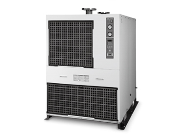
Refrigerant R407C (HFC) IDF100FS, IDF125FS, IDF150FS Series external appearance 2
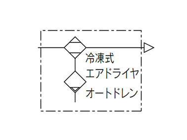
JIS symbol
Standard Specifications
| Specifications | Model | |||||
|---|---|---|---|---|---|---|
| IDF100FS-30 | IDF125FS-30 | IDF150FS-30 | ||||
| Operating range*1 | Applicable fluid | Compressed Air | ||||
| Inlet air temperature (°C) | 5 to 60 | |||||
| Inlet air pressure (MPa) | 0.15 to 1.0 / 0.15 to 1.6 (option K) | |||||
| Ambient temperature (humidity) (°C) | 2 to 45 (Relative humidity of 85% or less) | |||||
| Outlet air pressure dew point set range*2, *3) (°C) | 10 to 30 | |||||
| Rated conditions | Air flow capacity m3/min | Standard condition (ANR)*4 | 50 Hz | 16 | 20.1 | 25 |
| 60 Hz | 18.8 | 23.7 | 27 | |||
| Compressor intake condition*5 | 50 Hz | 16.7 | 20.9 | 26 | ||
| 60 Hz | 19.6 | 24.7 | 28.1 | |||
| Inlet air pressure (MPa) | 0.7 | |||||
| Inlet air temperature (°C) | 40 | |||||
| Ambient temperature (°C) | 32 | |||||
| Outlet air pressure dew point*6 (°C) | 10 | |||||
| Exhaust heat from condenser (50/60 Hz) (kW) | 7.5/8.7 | 9.2/10.8 | 10.4/12.4 | |||
| Electric specifications | Power supply voltage (frequency)*7 | Three-phase 200 V AC (50 Hz) / 200/220 V AC (60 Hz) | ||||
| Power consumption (50/60 Hz)*8 (kW) | 2.8/3.3 | 3.8/4.5 | 3.8/4.5 | |||
| Operating current (50/60 Hz)*8 (A) | 8.9/9.9 | 13.0/14.5 | 13.0/14.5 | |||
| Applicable circuit breaker capacity*9 (A) | 20 | 30 | ||||
| Condenser | Air-cooled | |||||
| Refrigerant | R407C (HFC) | |||||
| Refrigerant charge (kg) | 1.38 | 1.46 | 1.98 | |||
| Auto drain | Heavy-duty auto drain (normally open) | |||||
| Port size | R2 | JIS flange 65A/10K | JIS flange 80A/10K | |||
| Weight (kg) | 228 | 255 | 340 | |||
| Coating color | Body panel: urban white 1 Base: urban gray 2 | |||||
| Applicable compressor output (Reference) For screw type (kW) | 100 | 125 | 150 | |||
*1: The operating range does not guarantee use at the rated air flow capacity. If the operating conditions differ from the rated conditions, select the model referring to "Model Selection" in the manufacturer's catalog.
*2: This function is used to reduce the energy consumption of the dryer operation by changing the outlet air pressure dew point depending on the season and operating environment. As this is not a function for the purpose of setting the dew point of the outlet air pressure to the required dew point, the offset and stability of the dew point of the outlet air pressure are not guaranteed.
*3: It is not possible to set the dew point of the outlet air pressure higher than the dew point of the inlet air pressure. (This dryer does not have a humidifying function.) When the load (e.g. air flow rate, inlet air temperature) is small, the dew point of the outlet air pressure may be lower than the set dew point. When the load (e.g. air flow rate, inlet air temperature) is large, the dew point of the outlet air pressure may not decrease to the set dew point.
*4: Indicates the air flow capacity under the standard condition (ANR) (at 20°C, atmospheric pressure, relative humidity 65%).
*5: Indicates the air flow capacity converted by the compressor intake condition (at 32°C, atmospheric pressure).
*6: The dew point of the outlet air pressure shown in this table is the value that is obtained when the air flow rate, inlet air temperature, inlet air pressure and ambient temperature are stable. The stated dew point of the outlet air pressure may not be obtained in an unstable condition, such as soon after compressed air is supplied.
*7: The voltage fluctuation should be maintained within ±10% of the rated voltage.
*8: Value with a power supply voltage of 200 V.
*9: Install an earth leakage breaker with a sensitivity 30 mA.
Structure Principle Diagram (Air/Refrigerant Circuit)
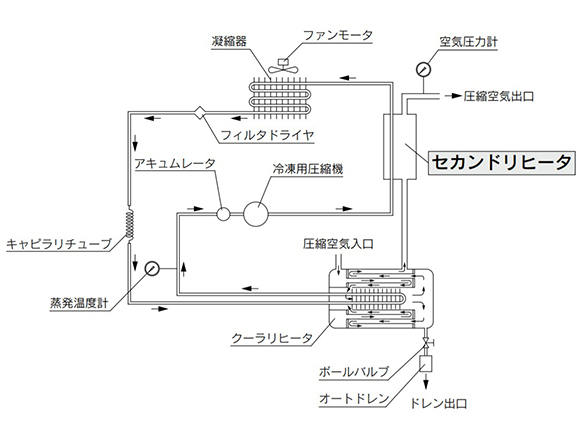
Structure Principle Diagram (Air/Refrigerant Circuit)
Humid, hot air coming into the air dryer is cooled down by a cooler re-heater (heat exchanger). Water condensed at this time will be drained out automatically by the auto drain. Air separated from the water is heated in 2 stages by a re-heater (heat exchanger) in the cooler re-heater and a secondary heater to obtain the dried warm air, which goes through to the outlet side.
Secondary heater
By heat exchanging the compressed air removed from the drain and the refrigerant compressed by the compressor, the following effects can be achieved:
- 1. Outlet air temperature is increased, securely preventing condensation at the output port.
- 2. Exhaust heat from condenser is reduced.
- 3. Reducing the exhaust heat from the condenser allows the dryer to save energy.
Structure and Dimensions
(Unit: mm)
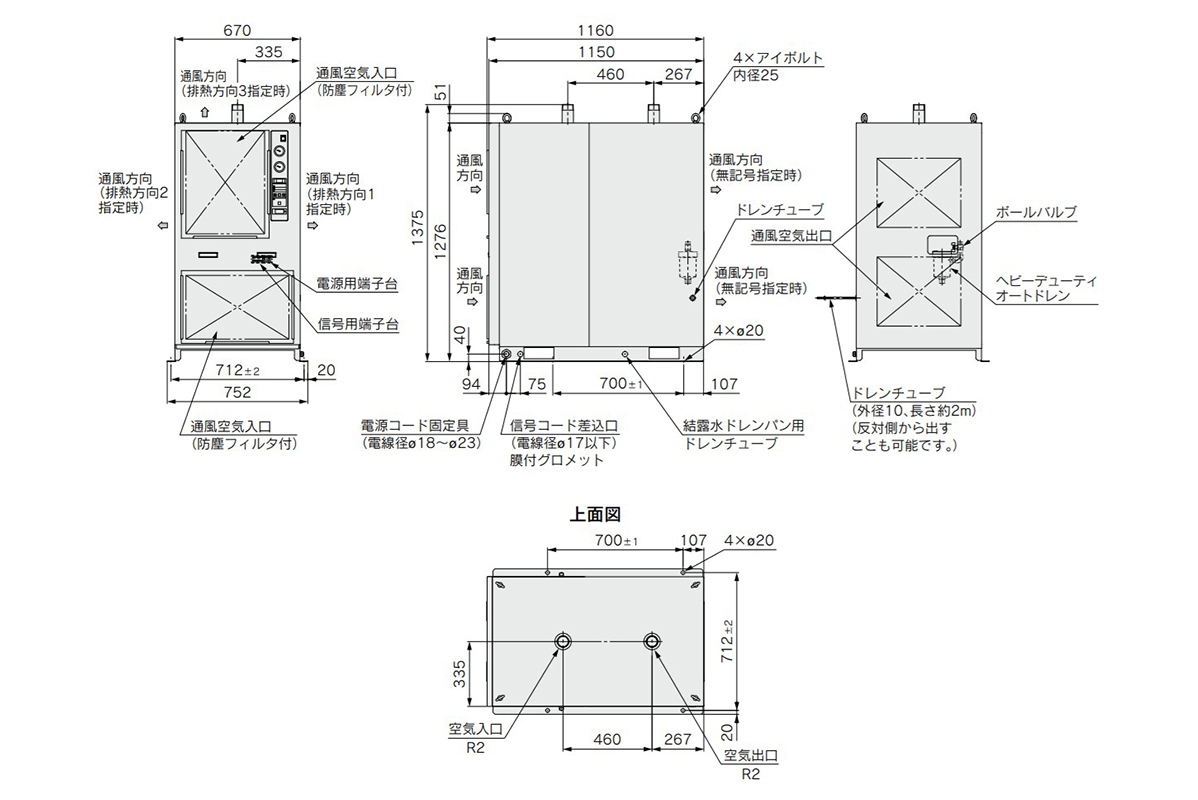
Structure and dimensional drawing: IDF100FS
(Unit: mm)
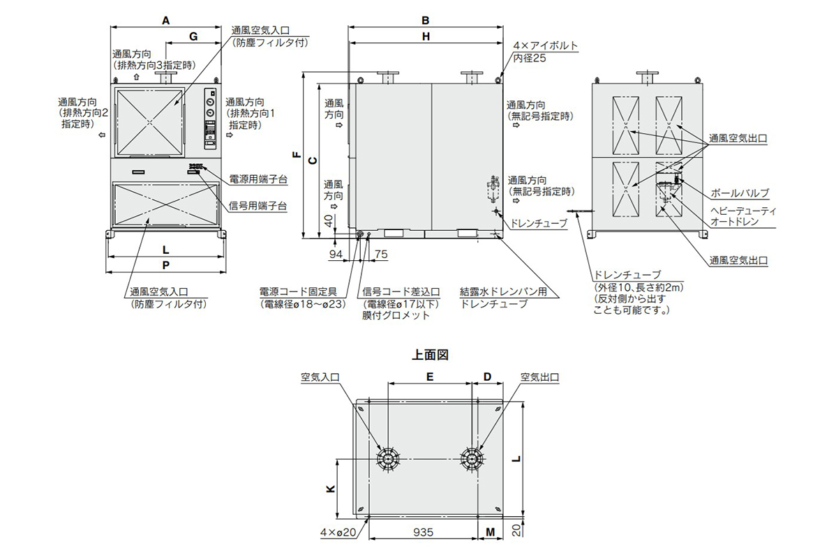
Structure and dimensional drawing: IDF125FS/150FS
(Unit: mm)
| Model | Port size | A | B | C | D | E | F | G | H | K | L | M | P |
|---|---|---|---|---|---|---|---|---|---|---|---|---|---|
| IDF125FS | JIS flange 65A/10K | 700 | 1,160 | 1,276 | 267 | 655 | 1,375 | 350 | 1,150 | 376 | 712 | 78 | 752 |
| IDF150FS | JIS flange 80A/10K | 950 | 1,330 | 1,332 | 268 | 720 | 1,432 | 475 | 1,320 | 515 | 990 | 217 | 1,030 |
Dimensional drawing: Slit
(Unit: mm)
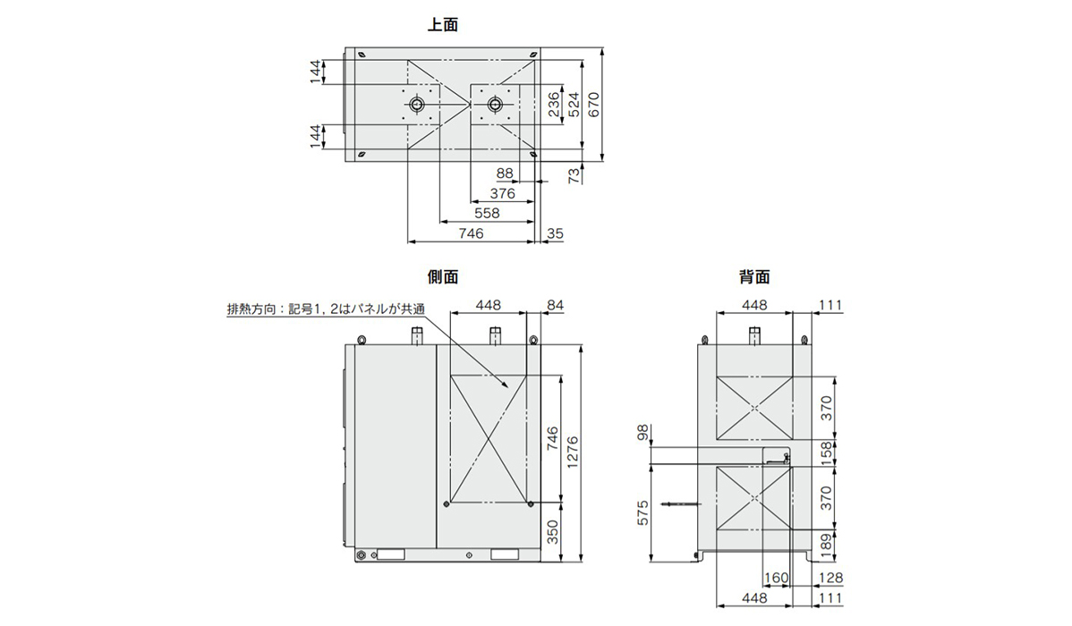
Dimensional drawing: IDF100FS slit
(Unit: mm)
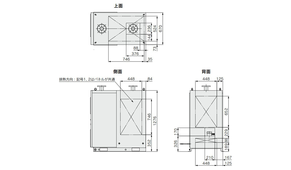
IDF125FS slit dimensional drawing
(Unit: mm)
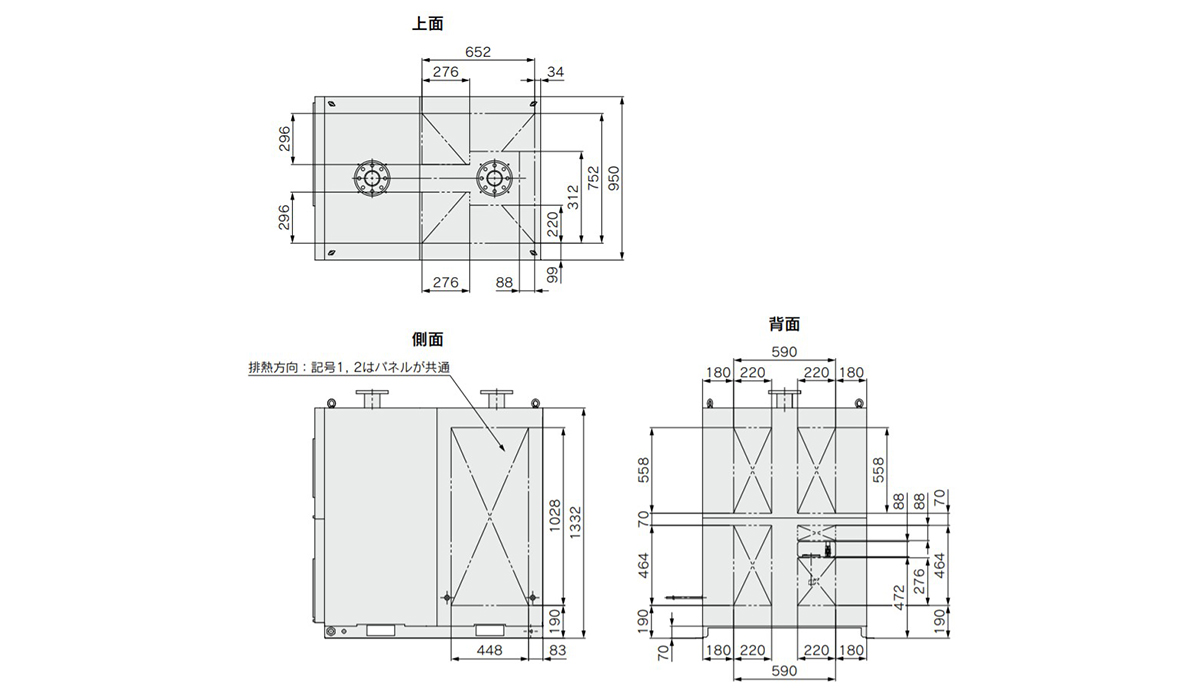
IDF150FS slit dimensional drawing
Precautions
- *The external appearance images are representative images.
- *See the manufacturer's catalog for product information other than the above.