Auto Hand Changing System (AHC), MA2 Series
Brand :
SMC
Caution
- See catalog for specification details.
- Product images may be representative images. Refer to the catalog for details.
Product Description
Automatic replacement of robot hand tools and FMS of assembly line.
[Features]
·No adjustment or teaching required when changing tools
·Accelerates the start-up of the assembly line
AHC System MA2 Series Features

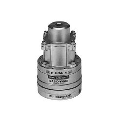
AHC System MA2 Series external appearance
Specifications
| Series | MA210 | ||
|---|---|---|---|
| Positioning | Ball coupling | ||
| Max. transportable weight | 3 kg | ||
| Handling | Single acting / air supply at separation | ||
| Handling air pressure | 0.4 to 0.7 MPa | ||
| Proof pressure | 1.05 MPa | ||
| Ambient and operating air temperature | 0 to 60°C | ||
| Positioning repeatability | ±0.01 mm | ||
| Combined axial force W* | 150N | ||
| Moment resistance M* | 2 N·m | ||
| Torque resistance T* | 2 N·m | ||
| Interface | Air | Maximum operating pressure | 0.7 MPa |
| Operating vacuum pressure | -100 kPa or more (10 Torr or more) | ||
| Cv factor | 0.056 | ||
| Number of circuits | 4 | ||
| Electricity | Contact point capacity | 2 A / interface | |
| Number of contact points | 8 | ||
- *Values given in the table for combined axial force, moment resistance and torque resistance are the values for when the AHC unit and the tool adapter begin to separate.
For safety reasons, make sure that the axial force, moment, and torque from the load are 1/2 or less than the values above during use.
Optional Part Nos.
Robot adapter
| Part no. | Applicable shaft diameter | Note |
|---|---|---|
| MA210-CS1 | ø8 (applicable shaft diameter 8 mm) | Hexagon socket head bolt M3 × 8 (4) M3 × 10 (4) |
| MA210-CR1 | ø10 (applicable shaft diameter 10 mm) | |
| MA210-CR2 | ø11 (applicable shaft diameter 11 mm) | |
| MA210-CR3 | ø14 (applicable shaft diameter 14 mm) | |
| MA210-CR4 | ø15 (applicable shaft diameter 15 mm) | |
| MA210-CR5 | ø20 (applicable shaft diameter 20 mm) |
Structural drawing / Parts list
Single Acting Type
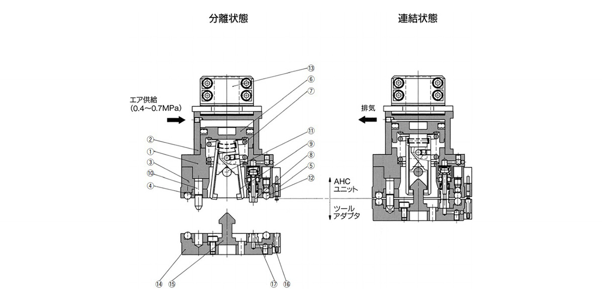
Single acting type, disconnected and connected structure drawing / component parts
Parts List
| Number | Part name | Material | Note |
|---|---|---|---|
| 1 | Unit body | Aluminum Alloy | Hard Anodize |
| 2 | Head cap | Aluminum Alloy | Hard Anodize |
| 3 | Ball base | Aluminum Alloy | Hard Anodize |
| 4 | Ball cover | Carbon steel | Electroless nickel plating |
| 5 | Contact probe ass’y | - | - |
| 6 | Piston | Stainless steel | - |
| 7 | Clamp spring | Steel wire | Zinc chromate |
| 8 | Check valve ass’y | - | - |
| 9 | Lever | Carbon steel | Special black thin-membrane anti-corrosive treated |
| 10 | Pilot pin | Carbon steel | Special black thin-membrane anti-corrosive treated |
| 11 | Parallel pin | Stainless steel | - |
| 12 | Steel ball | Stainless steel | - |
| 13 | Robot adapter | Aluminum Alloy | Hard Anodize |
| 14 | Tool adapter | Aluminum Alloy | Hard Anodize |
| 15 | Hook | Carbon steel | Special black thin-membrane anti-corrosive treated |
| 16 | Contact block ass’y | - | Contact point gold plated |
| 17 | Passage seal | Synthetic rubber | - |
Outline dimensional drawing
AHC Unit + Tool Adapter
- AHC unit / MA210-YNM3 (without robot adapter)
- AHC unit / MA210-YNM3-□ (with robot adapter)
- Tool adapter / MA210-AM3
(Unit: mm)
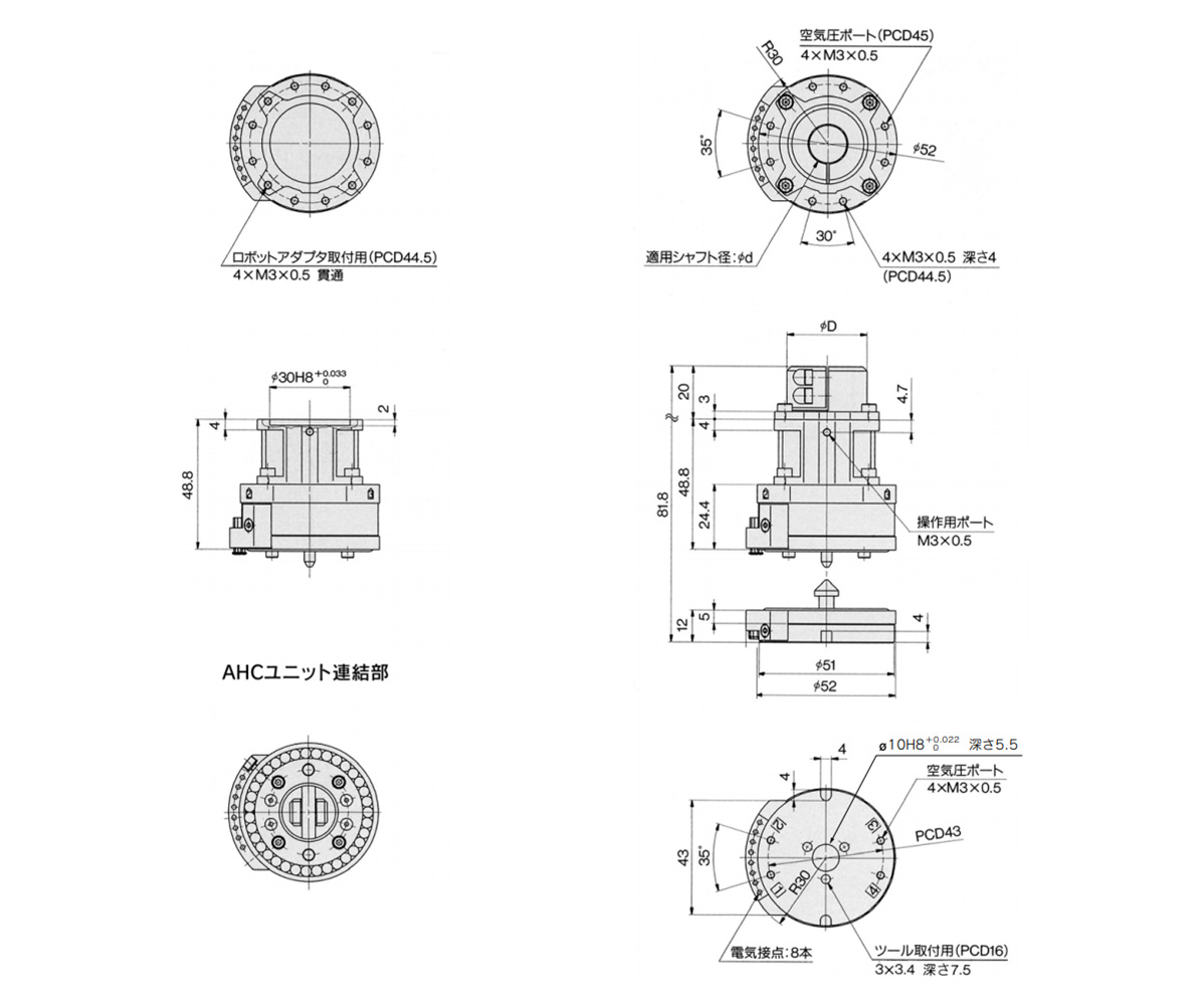
AHC unit / MA210-YNM3 (without robot adapter) AHC unit / MA210-YNM3-□ (with robot adapter) tool adapter / MA210-AM3 external dimensional drawing
(Unit: mm)
| Model | Applicable shaft diameter ød | øD | Weight g | |
|---|---|---|---|---|
| AHC Unit | MA210-YNM3 | - | - | 260 |
| MA210-YNM3-S1 | 8 | 25 | 300 | |
| MA210-YNM3-R1 | 10 | 30 | ||
| MA210-YNM3-R2 | 11 | |||
| MA210-YNM3-R3 | 14 | |||
| MA210-YNM3-R4 | 15 | |||
| MA210-YNM3-R5 | 20 | 35 | ||
| Tool adapter | MA210-AM3 | - | - | 100 |
Robot adapter
- MA210-C□□
(Unit: mm)
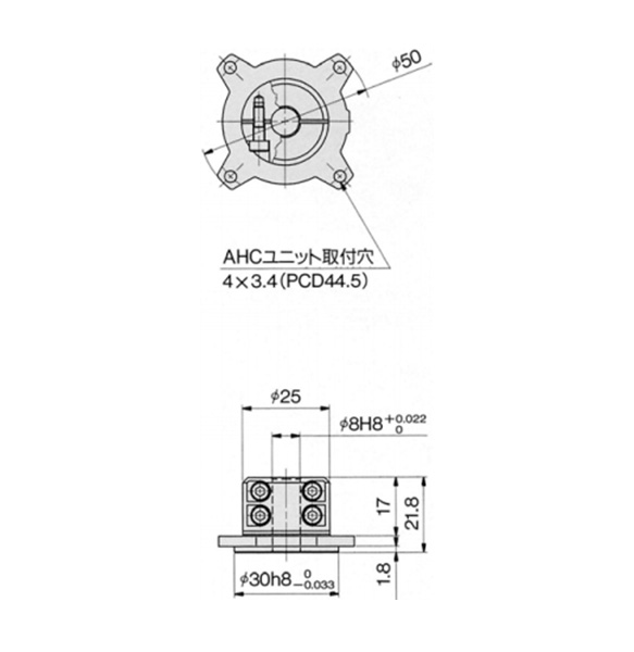
MA210-CS1 external dimensional drawing
(Unit: mm)
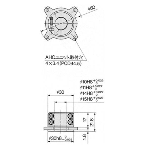
MA210-CR1, 2, 3, 4 external dimensional drawing
(Unit: mm)
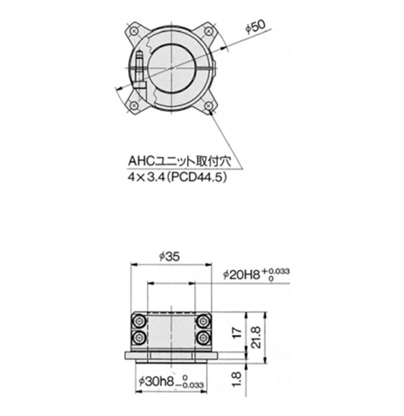
MA210-CR5 external dimensional drawing
(Unit: mm)
| Part number | Applicable shaft diameter | Weight g |
|---|---|---|
| MA210-CS1 | ø8 (applicable shaft diameter 8 mm) | 40 |
| MA210-CR1 | ø10 (applicable shaft diameter 10 mm) | |
| MA210-CR2 | ø11 (applicable shaft diameter 11 mm) | |
| MA210-CR3 | ø14 (applicable shaft diameter 14 mm) | |
| MA210-CR4 | ø15 (applicable shaft diameter 15 mm) | |
| MA210-CR5 | ø20 (applicable shaft diameter 20 mm) |
Tool Stand
(Unit: mm)
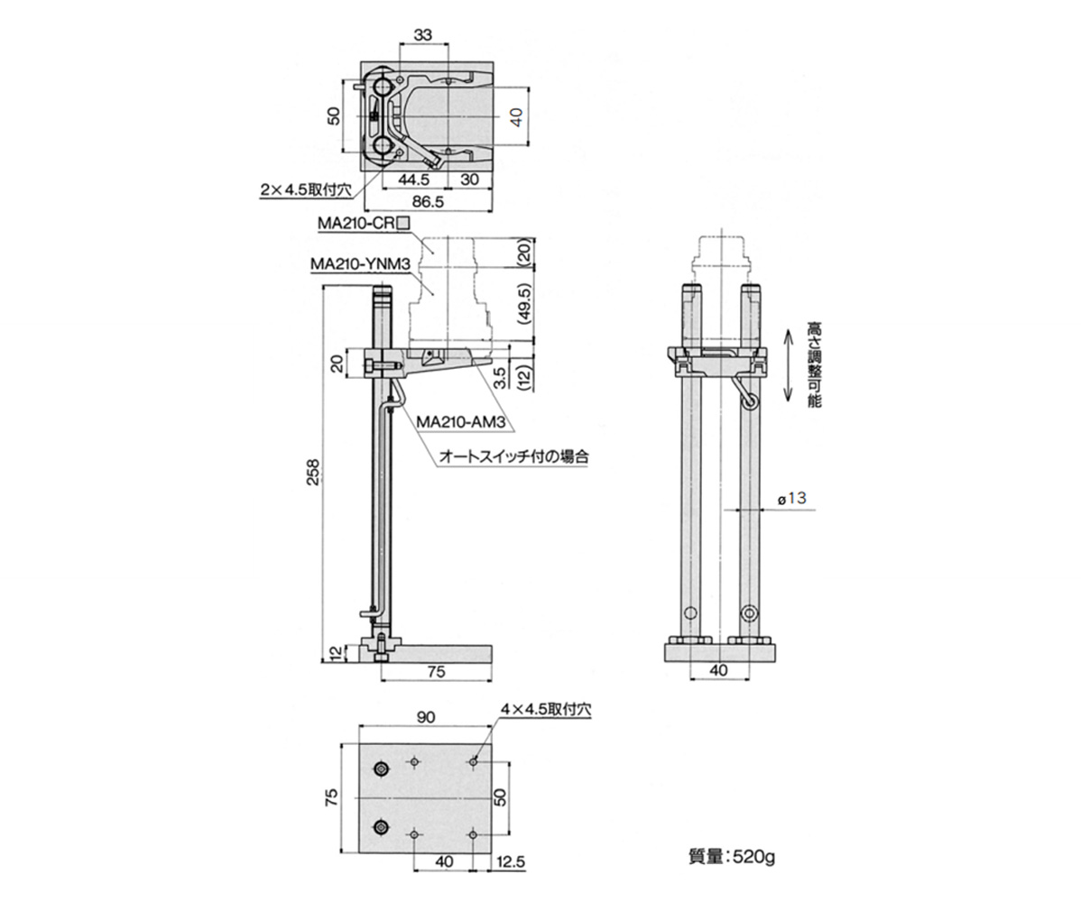
MA210-S1-□ external dimensional drawing
- *Refer to the manufacturer's catalog for other models' specifications, etc.