(!)Due to Microsoft's end of support for Internet Explorer 11 on 15/06/2022, this site does not support the recommended environment.
Instead, please kindly use other browsers like Google Chrome, Microsoft Edge or Mozilla Firefox.
50,000 Stock items for Same Day Ship Out.
All Categories
Categories
- Automation Components
A wide variety of standard and configurable components for factory automation engineers in industries such as automotive, semiconductor, packaging, medical and many more.
- Linear Motion
- Rotary Motion
- Connecting Parts
- Rotary Power Transmission
- Motors
- Conveyors & Material Handling
- Locating, Positioning, Jigs & Fixtures
- Inspection
- Sensors, Switches
- Pneumatics, Hydraulics
- Vacuum Components
- Hydraulic Equipment
- Discharging / Painting Devices
- Pipe, Tubes, Hoses & Fittings
- Modules, Units
- Heaters, Temperature Control
- Framing & Support
- Casters, Leveling Mounts, Posts
- Doors, Cabinet Hardware
- Springs, Shock Absorbers
- Adjusting, Fastening, Magnets
- Antivibration, Soundproofing Materials, Safety Products
- Fasteners
A good selection of accessories such as screws, bolts, washers and nuts that you may need for your daily engineering usage.
- Materials
Browse industrial materials ranging from heat insulating plates, sponges, to metal and plastic materials in different sizes to meet your various applications.
- Wiring Components
A wide variety of wiring parts for connecting and protecting control and PC parts including Connectors, Cables, Electric Wires, Crimping Terminals and more.
- LAN Cables / Industrial Network Cables
- Cables by Application
- Cables with Connectors
- RS232 / Personal Computers / AV Cables
- Wires/Cables
- Connectors (General Purpose)
- Crimp Terminals
- Zip Ties
- Cable Glands
- Cable Bushings/Clips/Stickers
- Screws/Spacers
- Cable Accessories
- Tubes
- Protection Tubes
- Ducts/Wiremolds
- General Purpose Tools
- Dedicated Tools
- Soldering Supplies
- Electrical & Controls
A wide variety of controls and PC parts for electrical engineers including Controls, Powers, PC parts and more.
- Cutting Tools
A wide variety of cutting tools for many uses and work materials including End Mills, Drills, Cutters, Reamers, Turning Tools and more.
- Carbide End Mills
- HSS End Mills
- Milling Cutter Inserts/Holders
- Customized Straight Blade End Mills
- Dedicated Cutters
- Turning Tools
- Drill Bits
- Screw-Hole-Related Tools
- Reamers
- Chamfering / Centering Tools
- Fixtures Related to Cutting Tools
- Step Drills
- Hole Saws
- Clean Key Cutters
- Core Drills (Tip Tools)
- Magnetic Drilling Machine Cutters
- Drill Bits for Electric Drilling Machines
- Woodworking Drill Cutters
- Drills for Concrete
- Processing Tools
A wide variety of tools and supplies used in processing including Machine Tools, Measurement Tools, Grinding and Polishing Supplies and more.
- Material Handling & Storage
A wide variety of goods used in shipment, material handling and warehouse including Tape supplies, Stretch film, Truck, Shelf, Crane and more.
- Tape Supplies
- Cushioning Materials
- Stretch Films
- Cardboard
- Plastic Bags
- PP Bands
- Magic Tapes / Tying Belts
- Rubber Bands
- Strings/Ropes
- Cable Ties
- Tags
- Labelers
- Unpacking Cutters
- Packing Support Equipment
- Cloth Sheets for Packing
- Conveyance/Dolly Carts
- Tool Wagons
- Tool Cabinets / Container Racks
- Lifters / Hand Pallets
- Container Pallets
- Storage Supplies
- Shelves/Racks
- Work Benches
- Suspended Clamps/Suspended Belts
- Jack Winches
- Chain Block Cranes
- Bottles/Containers
- Bicycle Storage Area
- Safety & General Supplies
A large variety of goods for every kind of factories and offices including Protection items, Cleaning supplies, sanitations, office supplies and more.
- Lab & Clean Room Supplies
A large variety of items used in R&D and Clean Room including research Equipment, Laboratory Essentials, Analysis Supplies, Clean Environment-Related Equipment and more.
- Press Die Components
Choose from thousands of standard stamping die components including Punch & Die, Gas Springs, Guide Components, Coil Springs and many more.
- Plastic Mold Components
Browse our wide variety of mold components including Ejector Pins, Sleeves, Leader Components, Sprue Bushings and many more.
- Ejector Pins
- Sleeves, Center Pins
- Core Pins
- Sprue bushings, Gates, and other components
- Date Mark Inserts, Recycle Mark Inserts, Pins with Gas Vent
- Undercut, Plates
- Leader Components, Components for Ejector Space
- Mold Opening Controllers
- Cooling or Heating Components
- Accessories, Others
- Components of Large Mold, Die Casting
- Injection Molding Components
Browse our injection molding components including Heating Items, Couplers, Hoses and more.
- Injection Molding Machine Products
- Accessories of Equipment
- Auxiliary Equipment
- Air Nippers
- Air Cylinders
- Air Chuck for Runner
- Chuck Board Components
- Frames
- Suction Components
- Parallel Air Chuck
- Special Air Chuck
- Chemical for Injection Molding
- Mold Maintenance
- Heating Items
- Heat Insulation Sheets
- Couplers, Plugs, One-touch Joints
- Tubes, Hoses, Peripheral Components
Search by Application
Brands


- Please Note our New Address (effective April 1, 2024): 331 North Bridge Rd, #05-01 Odeon 331, Singapore 188720.
Rubber Bushing for MS Connector Cable Clamp MMS3420

Click this image to zoom it.
Move the mouse over the image to zoom
- Volume Discount
[Specifications]·Low-cost type MS cable clamp rubber bushing
- MIL

<<Amazingly Low Price>>
● Check the price first.
● Can also be used for products from other manufacturers as long as they are cable clamps compliant with MIL standards.

· Rubber bushings come with the cable clamp. Select the same size when replacing rubber bushings. Select one size smaller than the accessory when using more than one.
Part Number
Configured Part Number is shown.
| Part Number |
|---|
| MMS3420-4 |
| MMS3420-6 |
| MMS3420-8 |
| MMS3420-10 |
| MMS3420-12 |
| MMS3420-16 |
| MMS3420-20 |
| MMS3420-24 |
| Part Number | Standard Unit Price | Minimum order quantity | Volume Discount | Days to Ship | Internal diameter (cable drawer slot diameter) (mm) |
|---|---|---|---|---|---|
SGD 2.37 | 1 Piece(s) | Available | 4 Day(s) or more | 5.59 | |
SGD 2.29 | 1 Piece(s) | Available | 4 Day(s) or more | 7.92 | |
SGD 2.31 | 1 Piece(s) | Available | 4 Day(s) or more | 11.10 | |
SGD 2.48 | 1 Piece(s) | Available | 4 Day(s) or more | 14.27 | |
SGD 2.90 | 1 Piece(s) | Available | 4 Day(s) or more | 15.88 | |
SGD 2.90 | 1 Piece(s) | Available | 4 Day(s) or more | 19.05 | |
SGD 3.02 | 1 Piece(s) | Available | 4 Day(s) or more | 23.80 | |
SGD 2.93 | 1 Piece(s) | Available | 4 Day(s) or more | 31.75 |
Loading...
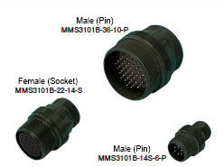
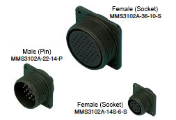
MIL Standards MS Connector
Common Specifications
Applied Wire Size and Contact Size
Applicable wire coating strip length is about 1 to 3 mm plus the soldering hole length (L dimension) of the contact. In addition, the L dimension and D dimension are the same for the male connector (pin) and female connector (socket). Also, confirm whether the cable will fit into the internal diameter of the cable clamp when selecting cables.| Contact | Conforming wire size | ||||
|---|---|---|---|---|---|
| Contact size | Soldering Hole Diameter øD (mm) | Pin Contact Contacting Part Diameter øA (mm) | L (mm) | AWG | Conductor Cross-Sectional Area (mm2) |
| #16 | 1.85 | 1.6 | 6.4 | 16 to 20 | 1.25 or Less |
| #12 | 2.95 | 2.4 | 9.5 | 12 to 14 | 3.5 or Less |
| #8 | 5.31 | 3.6 | 12.7 | 8 to 10 | 8 or Less |
| #4 | 8.45 | 5.7 | 15.9 | 4 to 6 | 22 or Less |
| #0 | 11.91 | 9.1 | 15.9 | 0 to 2 | 50 or Less |
Electrical Characteristics
| Contact Resistance | Contact size | Test Current DC | Voltage drop | Meets the left value when it is measured with the fall-of-potential test method where the male and female connectors are coupled in the same way as in use and a test current is energized. |
|---|---|---|---|---|
| #16 | 20 A | 21 mV or less | ||
| #12 | 35 A | 20 mV or less | ||
| #8 | 60 A | 12 mV or less | ||
| #4 | 110 A | 10 mV or less | ||
| #0 | 200 A | 10 mV or less |
Mechanical Characteristics
| Temperature Shock | Low Temperature | High Temperature | Consider the left low temperature and high temperature as one cycle and continuously perform 5 cycles. Leave low temperature and high temperature for 30 minutes or more. | ||||
|---|---|---|---|---|---|---|---|
| -55 +0°C | +125 +3°C | ||||||
| (1) There is no crack or breakage in connectors. (2) The withstand voltage test is passed after completion. | |||||||
| Humidity Resistance | Meets the following withstand voltage. | After exposing a pair of a connected connector and panel mount to a temperature of 71 ± 2°C and a relative humidity of 95 ± 3% for 14 days, perform the withstand voltage test listed in the left table for 5 minutes without drying. | |||||
| Test Classification Symbol | VAC (RMS) | ||||||
| INST | 300 | ||||||
| A | 750 | ||||||
| D | 1,350 | ||||||
| E | 1,875 | ||||||
| B | 2,775 | ||||||
| C | 4,500 | ||||||
| Corrosion | (1) There is no corrosion to damage the connection or separation of connectors, or base metal exposure. (2) Contact resistance measurement | After exposure to a salt spray at a temperature of 35°C and a concentration of 5% for 48 hours, wash with water, dry by leaving in an air circulation tank for 12 hours at 38 ±3°C, and then perform contact resistance and withstand voltage tests. | |||||
| Contact size | Test Current | Voltage drop (or less) | |||||
| #16 | 20A | 35 mV | |||||
| #12 | 35 | 30 | |||||
| #8 | 60 | 25 | |||||
| #4 | 110 | 20 | |||||
| #0 | 200 | 20 | |||||
| (3) Meets the following withstand voltage. | |||||||
| Test Classification Symbol | VAC (RMS) | Classification Symbol | VAC (RMS) | ||||
| INST | 400 | E | 2,500 | ||||
| A | 1,000 | B | 3,500 | ||||
| D | 1,800 | C | 6,000 | ||||
Environmental Characteristics
| Contact Single Unit Insertion/Removal Force | Contact size | Average | Maximum | Minimum | Measure insertion/removal force with a randomly chosen male and female. The average force must be the average value shown at left or less, 96% of all values must be the maximum value or less, and all values must be the minimum value or more. |
|---|---|---|---|---|---|
| #16 | 0.95 kg | 1.36 kg | 0.11 kg | ||
| #12 | 1.59 | 2.27 | 0.23 | ||
| #8 | 3.18 | 4.54 | 0.34 | ||
| #4 | 4.76 | 6.8 | 0.45 | ||
| #0 | 6.35 | 9.07 | 0.91 | ||
| Contact Holding Force | Contact size | Axial Load (kg) | Contact size | Axial Load (kg) | Withstands axial load in both directions shown at left. |
| #16 | 4.5 | #4 | 9.1 | ||
| #12 | 6.8 | #0 | 11.3 | ||
| #8 | 9.1 | ||||
| Vibration | (1) There is no current break for 10 μsec or more during the test. (2) The withstand voltage test is passed after completion. (3) There is no disconnection, crack or breakage in any part. | Couple a connector and a panel mount connected with wire in the normal way and perform a vibration test with MIL-STD-1344. Apply 100 mA current to the connector, check for current break in an appropriate way, and then perform a withstand voltage test and an external appearance test. | |||
| Shock | (1) Meets the required contact resistance after completion. (2) There is no crack, breakage, or looseness in any part. | Apply an acceleration of 50 G to the connector and the panel mount connected with wire at an angle of 90 degrees to each axial direction. | |||
| Life | (1) Meets the contact resistance requirements. (2) There is no electrical or mechanical abnormality. | Remove the coupling nut from the connector and perform insertion and removal 500 times at a speed not above 600 times per hour. | |||
Contact arrangement table (in order of core number), a view from the coupling surface of the male (pin) connector.
Arrangement No.
The shell size of the entire connector is at left. The arrangement number of its contacts is at right. Together they comprise the Arrangement No.
Configuration of Number of Cores
The size per contact is shown on the right. The number of contacts is shown on the left.
| Arrangement No. | Contact Shape | Contact Configuration | Rated Current (A) (Note 1) | Insulation Resistance MΩ (or more) | Rated Voltage (*2) (*3) | Test Classification (Note 4) | ||||
|---|---|---|---|---|---|---|---|---|---|---|
| Shell Size | Arrangement Number | Total Number of Cores | Configuration of Number of Cores | Contact Size | VDC or less Characters are Contact No. | VAC (RMS) or less Characters are Contact No. ( ) is Withstand Voltage / VAC (RMS) | ||||
| 10SL | 3 | P Male (Pin) S Female (Socket) | 3 | 3 | #16 | 13 | 5,000 | 700 | 500 (2,000) | A |
| 4 | 2 | 2 | ||||||||
| 12S | 3 | 2 | 2 | |||||||
| 14S | 1 | 3 | 3 | |||||||
| 2 | 4 | 4 | 250 | 200 (1,000) | INST | |||||
| 5 | 5 | 5 | ||||||||
| 6 | 6 | 6 | ||||||||
| 7 | 3 | 3 | 700 | 500 (2,000) | A | |||||
| 9 | 2 | 2 | ||||||||
| 16S | 1 | 7 | 7 | |||||||
| 5 | 3 | 3 | ||||||||
| 8 | 5 | 5 | ||||||||
| 16 | 10 | 3 | 3 | #12 | 23 | |||||
| 18 | 1 | 10 | 10 | #16 | 13 | BCFG-700, Other-250 | BCFG-500 (2,000),Other-200 (1,000) | A (BCFG) INST (Other) | ||
| 4 | 4 | 4 | 1,250 | 900 (2,800) | D | |||||
| 5 | 3 | 2 | #12 | 23 | ||||||
| 1 | #16 | 13 | ||||||||
| 8 | 8 | 1 | #12 | 23 | 700 | 500 (2,000) | A | |||
| 7 | #16 | 13 | ||||||||
| 10 | 4 | 4 | #12 | 23 | ||||||
| 11 | 5 | 5 | ||||||||
| 12 | 6 | 6 | #16 | 13 | ||||||
| 19 | 10 | 10 | ||||||||
| 20 | 5 | 5 | ||||||||
| 21 | 3 | 3 | #12 | 23 | ||||||
| 22 | 3 | 3 | #16 | 13 | 1,250 | 900 (2,800) | D | |||
| 20 | 2 | 1 | 1 | #0 | 150 | ABHG-1250, CDEF-700 | ABHG-900 (2,800), CDEF-500 (2,000) | D (ABHG) A (CDEF) | ||
| 4 | 4 | 4 | #12 | 23 | 700 | 500 (2,000) | A | |||
| 7 | 8 | 8 | #16 | 13 | ||||||
| 15 | 7 | 7 | #12 | 23 | ||||||
| 16 | 9 | 2 | ||||||||
| 7 | #16 | 13 | ||||||||
| 17 | 6 | 5 | #12 | 23 | ||||||
| 1 | #16 | 13 | ||||||||
| 18 | 9 | 3 | #12 | 23 | ||||||
| 6 | #16 | 13 | ||||||||
| 22 | 6 | 3 | #8 | 46 | ||||||
| 3 | #16 | 13 | ||||||||
| 23 | 2 | 2 | #8 | 46 | ||||||
| 27 | 14 | 14 | #16 | 13 | ||||||
| 29 | 17 | 17 | ||||||||
| 22 | 2 | 3 | 3 | #8 | 46 | 1,250 | 900 (2,800) | D | ||
| 10 | 4 | 4 | #16 | 13 | 1,750 | 1,250 (3,500) | E | |||
| 14 | 19 | 19 | 700 | 500 (2,000) | A | |||||
| 19 | 14 | 14 | ||||||||
| 22 | 4 | 4 | #8 | 46 | ||||||
| 23 | 8 | 8 | #12 | 23 | H-1250, Other-700 | H-900 (2,800), Other-500 (2,000) | D (H) A (Other) | |||
| 28 | 7 | 7 | 700 | 500 (2,000) | A | |||||
| 24 | 2 | 7 | 7 | 1,250 | 900 (2,800) | D | ||||
| 5 | 16 | 16 | #16 | 13 | 700 | 500 (2,000) | A | |||
| 7 | 16 | 2 | #12 | 23 | ||||||
| 14 | #16 | 13 | ||||||||
| 10 | 7 | 7 | #8 | 46 | ||||||
| 11 | 9 | 3 | ||||||||
| 6 | #12 | 23 | ||||||||
| 20 | 11 | 2 | 1,250 | 900 (2,800) | D | |||||
| 9 | #16 | 13 | ||||||||
| 22 | 4 | 4 | #8 | 46 | ||||||
| 28 | 24 | 24 | #16 | 13 | 250 | 200 (1000) | INST | |||
| 28 | 6 | P Male (Pin) S Female (Socket) | 3 | 3 | #4 | 80 | 5,000 | 1,250 | 900 (2,800) | D |
| 10 | 7 | 2 | G-1250, Other-700 | G-900 (2,800), 2 #8 46 Other-500 (2,000) | D (G) A (Other) | |||||
| 2 | #8 | 46 | ||||||||
| 3 | #12 | 13 | ||||||||
| 11 | 22 | 4 | 700 | 500 (2,000) | A | |||||
| 18 | #16 | 13 | ||||||||
| 12 | 26 | 26 | ||||||||
| 15 | 35 | 35 | ||||||||
| 16 | 20 | 20 | ||||||||
| 20 | 14 | 10 | #12 | 23 | ||||||
| 4 | #16 | 13 | ||||||||
| 21 | 37 | 37 | ||||||||
| 32 | 1 | 5 | 2 | #0 | 150 | A-1750, Other-1250 | A-1250 (3,500), Other-900 (2,800) | (A) D (Other) | ||
| 3 | #12 | 23 | ||||||||
| 2 | 5 | 3 | #4 | 80 | 1,750 | 1,250 (3,500) | E | |||
| 2 | #16 | 13 | ||||||||
| 5 | 2 | 2 | #0 | 150 | 1,250 | 900 (2,800) | D | |||
| 7 | 35 | 7 | #12 | 23 | ABhj-250, Other-700 | ABhj-200 (1,000) Other-500 (2,000) | INST (ABhj) A (Other) | |||
| 28 | #16 | 13 | ||||||||
| 8 | 30 | 6 | #12 | 23 | 700 | 500 (2,000) | A | |||
| 24 | #16 | 13 | ||||||||
| 9 | 14 | 2 | #4 | 80 | 1,250 | 900 (2,800) | D | |||
| 12 | #16 | 13 | ||||||||
| 32A | 10 | 54 | 54 | 700 | 500 (2,000) | A | ||||
| 32 | 17 | 4 | 4 | #4 | 80 | 1,250 | 900 (2,800) | D | ||
| 414 | 52 | 52 | #16 | 13 | 700 | 500 (2,000) | A | |||
| 36 | 3 | 6 | 3 | #0 | 150 | 1,250 | 900 (2,800) | D | ||
| 3 | #12 | 23 | ||||||||
| 4 | 3 | 3 | #0 | 150 | A-1250, BC-700 | A-900 (2,800), BC-500 (2,000) | D (A) A (BC) | |||
| 5 | 4 | 4 | 700 | 500 (2,000) | A | |||||
| 9 | 31 | 1 | #4 | 80 | ||||||
| 2 | #8 | 46 | ||||||||
| 14 | #12 | 23 | ||||||||
| 14 | #16 | 13 | ||||||||
| 10 | 48 | 48 | ||||||||
| 73 | 73 | 73 | ||||||||
| 48 | 5 | 100 | 1 | #8 | 46 | |||||
| 9 | #12 | 23 | ||||||||
| 90 | #16 | 13 | ||||||||
*2: The rated voltage will change depending on contact arrangement rather than on the size of contacts or shells.
*3 The rated voltage may be different with each contact even in the same connector.
*4 Characteristics will change depending on test classification.
Key Position (Angle) Change for Prevention of Mistaken Insertion
Straight Connector

Outline Drawing
| Shell Size | Coupling Screw A Thread | Dimensions (mm) | |||||
|---|---|---|---|---|---|---|---|
| Cable Entry øB ±0.3 | Effective Thread Length J ±0.3 | Overall Length L or less | Outer Diameter Q ±0.8 | Conduit Screw V Thread | Thread Length W or more | ||
| 10SL | 5/8-24UNEF-2B | 9.6 | 13.49 | 34.9 | 22.22 | 5/8-24UNEF-2A | 9.53 |
| 12S | 3/4-20UNEF-2B | 9.6 | 13.5 | 42.8 | 25.4 | 5/8-24UNEF-2A | 9.5 |
| 14S | 7/8-20UNEF-2B | 12.5 | 13.5 | 42.8 | 28.6 | 3/4-20UNEF-2A | 9.5 |
| 16S | 1-20UNEF-2B | 15.6 | 13.5 | 42.8 | 31.8 | 7/8-20UNEF-2A | 9.5 |
| 16 | 1-20UNEF-2B | 15.6 | 18.3 | 52.4 | 31.8 | 7/8-20UNEF-2A | 9.5 |
| 18 | 1-1/8-18UNEF-2B | 20.2 | 18.3 | 52.4 | 34.1 | 1-20UNEF-2A | 9.5 |
| 20 | 1-1/4-18UNEF-2B | 23.0 | 18.3 | 55.6 | 37.3 | 1-3/16-18UNEF-2A | 9.5 |
| 22 | 1-3/8-18UNEF-2B | 23.2 | 18.3 | 55.6 | 40.5 | 1-3/16-18UNEF-2A | 9.5 |
| 24 | 1-1/2-18UNEF-2B | 29.5 | 18.3 | 58.7 | 43.7 | 1-7/16-18UNEF-2A | 9.5 |
| 28 | 1-3/4-18UNS-2B | 29.8 | 18.3 | 58.7 | 50.0 | 1-7/16-18UNEF-2A | 9.5 |
| 32 | 2-18UNS-2B | 37.5 | 18.3 | 61.9 | 56.4 | 1-3/4-18UNS-2A | 11.1 |
| 36 | 2-1/4-16UN-2B | 43.8 | 18.3 | 61.9 | 62.7 | 2-18UNS-2A | 12.7 |
| 48 | 3-16UN-2B | 69.1 | 18.3 | 65.1 | 81.8 | 3-16UN-2A | 15.9 |
Angle Connector

Outline Drawing
| Shell Size | Coupling Screw A Thread | Dimensions (mm) | |||||||
|---|---|---|---|---|---|---|---|---|---|
| Cable Entry B ±0.3 | Effective Thread Length J ±0.3 | Overall Length L or less | M ±0.8 | Outer Diameter Q ±0.8 | U ±0.8 | Conduit Screw V Thread | Thread Length W or more | ||
| 12S | 3/4-20UNEF-2B | 9.6 | 13.5 | 50.8 | 41.7 | 25.4 | 25.4 | 5/8-24UNEF-2A | 9.5 |
| 14S | 7/8-20UNEF-2B | 12.5 | 13.5 | 54.0 | 43.3 | 28.6 | 27.0 | 3/4-20UNEF-2A | 9.5 |
| 16S | 1-20UNEF-2B | 15.6 | 13.5 | 60.3 | 48.0 | 31.8 | 28.6 | 7/8-20UNEF-2A | 9.5 |
| 16 | 1-20UNEF-2B | 15.6 | 18.3 | 65.1 | 52.8 | 31.8 | 28.6 | 7/8-20UNEF-2A | 9.5 |
| 18 | 1-1/8-18UNEF-2B | 18.6 | 18.3 | 68.3 | 54.4 | 34.1 | 32.1 | 1-20UNEF-2A | 9.5 |
| 20 | 1-1/4-18UNEF-2B | 23.0 | 18.3 | 77.0 | 60.7 | 37.3 | 33.7 | 1-3/16-18UNEF-2A | 9.5 |
| 22 | 1-3/8-18UNEF-2B | 23.2 | 18.3 | 77.0 | 60.7 | 40.5 | 33.3 | 1-3/16-18UNEF-2A | 9.5 |
| 24 | 1-1/2-18UNEF-2B | 28.0 | 18.3 | 86.5 | 67.1 | 43.7 | 34.9 | 1-7/16-18UNEF-2A | 9.5 |
| 28 | 1-3/4-18UNS-2B | 28.2 | 18.3 | 86.5 | 67.1 | 50.0 | 38.5 | 1-7/16-18UNEF-2A | 9.5 |
| 32,32A | 2-18UNS-2B | 35.9 | 18.3 | 95.2 | 71.8 | 56.4 | 46.4 | 1-3/4-18UNS-2A | 11.1 |
| 36 | 2-1/4-16UN-2B | 42.2 | 18.3 | 100.0 | 73.4 | 62.7 | 51.2 | 2-18UNS-2A | 12.7 |
| 48 | 3-16UN-2B | 65.9 | 18.3 | 125.4 | 86.5 | 81.8 | 59.1 | 3-16UN-2A | 15.9 |
Relay Connector
Outline Drawing

| Shell Size | Coupling Screw A Thread | Dimensions (mm) | |||||
|---|---|---|---|---|---|---|---|
| Effective Thread B or more | Overall Length L or less | Length to Flange M +0.4 -0 | Outer Diameter N or less | Conduit Screw V Thread | Thread Length W or more | ||
| 12S | 3/4-20UNEF-2A | 9.5 | 42.88 | 14.3 | 26.97 | 5/8-24UNEF-2A | 25.4 |
| 14S | 7/8-20UNEF-2A | 9.5 | 42.88 | 14.3 | 29.36 | 3/4-20UNEF-2A | 27.0 |
| 16S | 1-20UNEF-2A | 9.5 | 42.88 | 14.3 | 31.75 | 7/8-20UNEF-2A | 28.6 |
| 16 | 1-20UNEF-2A | 15.9 | 52.37 | 19.0 | 31.75 | 7/8-20UNEF-2A | 28.6 |
| 18 | 1-1/8-18UNEF-2A | 15.9 | 52.37 | 19.0 | 34.14 | 1-20UNEF-2A | 32.1 |
| 20 | 1-1/4-18UNEF-2A | 15.9 | 55.58 | 19.0 | 37.31 | 1-3/16-18UNEF-2A | 33.7 |
| 22 | 1-3/8-18UNEF-2A | 15.9 | 55.58 | 19.0 | 40.49 | 1-3/16-18UNEF-2A | 33.3 |
| 24 | 1-1/2-18UNEF-2A | 15.9 | 58.72 | 19.0 | 43.66 | 1-7/16-18UNEF-2A | 34.9 |
| 28 | 1-3/4-18UNS-2A | 15.9 | 58.72 | 19.0 | 50.01 | 1-7/16-18UNEF-2A | 38.5 |
| 32,32A | 2-18UNS-2A | 15.9 | 61.93 | 19.0 | 56.36 | 1-3/4UNS-2A | 46.4 |
| 36 | 2-1/4-16UN-2A | 15.9 | 61.93 | 19.0 | 62.71 | 2-18UNS-2A | 51.2 |
| 48 | 3-16UN-2A | 15.9 | 65.07 | 15.9 | 81.76 | 3-16UN-2A | 59.1 |
Panel Mount
Outline Drawing

| Shell Size | A Thread | Dimensions (mm) | |||||||
|---|---|---|---|---|---|---|---|---|---|
| B or more | K or less | L or less | M +0.79 | øN +0 | R ±0.13 | S ±0.79 | øT +0.25 | ||
| 10SL | 5/8-24UNEF-2A | 9.53 | 2.1 | 21.9 | 14.28 | 15.9 | 18.26 | 25.4 | 3.05 |
| 12S | 3/4-20UNEF-2A | 9.52 | 2.4 | 24.3 | 14.27 | 19.86 | 20.62 | 27.79 | 3.05 |
| 14S | 7/8-20UNEF-2A | 9.52 | 2.4 | 24.3 | 14.27 | 23.01 | 23.01 | 30.18 | 3.05 |
| 16S | 1-20UNEF-2A | 9.52 | 2.4 | 24.3 | 14.27 | 24.61 | 24.61 | 32.54 | 3.05 |
| 16 | 1-20UNEF-2A | 15.88 | 2.4 | 29.1 | 19.05 | 24.61 | 24.61 | 32.54 | 3.05 |
| 18 | 1-1/8-18UNEF-2A | 15.88 | 3.0 | 28.6 | 19.05 | 26.97 | 26.97 | 34.92 | 3.05 |
| 20 | 1-1/4-18UNEF-2A | 15.88 | 3.0 | 29.4 | 19.05 | 29.36 | 29.36 | 38.10 | 3.05 |
| 22 | 1-3/8-18UNEF-2A | 15.88 | 3.0 | 29.4 | 19.05 | 31.75 | 31.75 | 41.28 | 3.05 |
| 24 | 1-1/2-18UNEF-2A | 15.88 | 3.0 | 33.4 | 20.62 | 34.92 | 34.92 | 44.45 | 3.73 |
| 28 | 1-3/4-18UNS-2A | 15.88 | 3.0 | 33.4 | 20.62 | 39.67 | 39.67 | 50.80 | 3.73 |
| 32,32A | 2-18UNS-2A | 15.88 | 4.3 | 33.4 | 22.22 | 44.45 | 44.45 | 57.15 | 4.39 |
| 36 | 2-1/4-16UN-2A | 15.88 | 4.3 | 33.4 | 22.22 | 49.23 | 49.23 | 63.50 | 4.39 |
| 48 | 3-16UN-2A | 15.88 | 4.3 | 34.2 | 22.22 | 66.68 | 66.68 | 82.55 | 4.39 |

Current Capacity Applicable to Entire Connector
| Total Number of Cores | 1 | 2 | 3 | 4 | 5 | 6 | 7 | 8 | 9 | 10 | 11 | 12 | 13 | 14 |
|---|---|---|---|---|---|---|---|---|---|---|---|---|---|---|
| Reduction Ratio (%) | 1 | 0.943 | 0.886 | 0.829 | 0.771 | 0.714 | 0.657 | 0.6 | 0.543 | 0.486 | 0.429 | 0.371 | 0.314 | 0.257 |
Rated current per contact x number of cores x reduction ratio = entire connector allowable current
13 A x 2 cores x 0.943 = 24.518 A
(For Arrangement No. 12S-3)
Therefore, 24.518 A can be applied to the whole connector.
(A contact rated current x number of A contact cores + B contact rated current x number of B contact cores) x reduction ratio (for total number of cores) = entire connector allowable current
(23 A x 2 cores + 13 A x 7 cores) x 0.543 = 74.391 A
(For Arrangement No. 20-16)
Therefore, 74.391 A can be applied to the whole connector.
Contact rated current x number of cores x 20% = entire connector allowable current
13 A x 17 cores x 0.2 = 44.2 A
(For Arrangement No. 20-29)
Therefore, 44.2 A can be applied to the whole connector.
(A contact rated current x number of A contact cores + B contact rated current x number of B contact cores) x 20% = entire connector allowable current
(23 A x 4 cores + 13 A x 18 cores) x 0.2 = 65.2 A
(For Arrangement No. 28-11)
Therefore, 65.2 A can be applied to the whole connector.
Soldering Method

Basic Information
| Type | Other | Color | Black |
|---|
- The specifications and dimensions of some parts may not be fully covered. For exact details, refer to manufacturer catalogs .
Tech Support
- Factory Automation, Electronics, Tools, & MRO (Maintenance, Repair and Operations)
- Tel:(65) 6733 7211 / FAX:(65) 6733 0211
- 9:00am - 6:00pm (Monday - Friday)
- Technical Inquiry
Payment Method
- Credit Card
- PayPal
- Bank Transfer
Social Media
MISUMI Contact
Copyright © MISUMI Corporation All Rights Reserved.
How can we improve?
How can we improve?