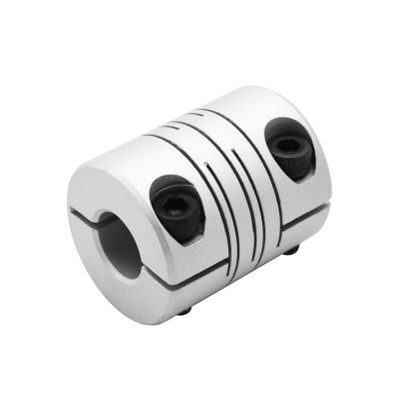
Slit Couplings Long, Clamping Type
Brand :
MISUMI
Caution
Product Description
This is an economy item, The price is cheaper than the MISUMI standard product.
Product Overview
■ Feature
・Flexible Shaft Couplings zero backlash
・Flexible Shaft Couplings with completely integrated structure, featuring slits in cylindrical hub.
・Flexible Shaft Couplings extremely high torsional stiffness and low moment of inertia.
・The leaf springs formed by the slits allow for eccentricity, angular misalignment, and Axial Misalignment.
・Flexible Shaft Couplings suitable for use in actuators, precision XY stages, indexing tables, etc.
Dimensional Drawing

Material table
| Type |  Material Material |  Surface Treatment Surface Treatment |  Accessory Accessory |
| E-LMPLCN | Aluminum Alloy | Clear Anodized | Hexagon socket bolts |
Specification Table
Please follow the selection steps ~
~ to select the part no. Specify Shaft Hole Dia. in therange d1≤d2.
 ~
~ to select the part no. Specify Shaft Hole Dia. in therange d1≤d2.
Part No.(Type· D) D) | - |  d1 d1 | - | d2 |
| E-LMPLCN16 | - | 3 | - | 4 |
| E-LMPLCN20 | - | 4 | - | 4.5 |
■ Specification
| Part Number |  d1、 d1、 d2 Shaft Hole Dia( d1≤d2) d2 Shaft Hole Dia( d1≤d2) | L | LF | F | Shaft Hole Dia. Φd | Clamp Screw | A | ||||||||||||||||||||||||||||
 Type Type |  D D | ||||||||||||||||||||||||||||||||||
| E-LMPLCN | 12 | 3 | 4 | 5 | 6 | . | 18.5 | 5.5 | 2.9 | Φ3-Φ4 | M2 | 3.3 | |||||||||||||||||||||||
| Φ5 | M2 | 3.8 | |||||||||||||||||||||||||||||||||
| Φ6 | M2 | 4.3 | |||||||||||||||||||||||||||||||||
| 16 | 3 | 4 | 5 | 6 | 6.35 | 7 | 8 | 23 | 6.3 | 3.2 | Φ3-Φ6.35 | M2.5 | 4.5 | ||||||||||||||||||||||
| Φ7-Φ8 | M2.5 | 5.7 | |||||||||||||||||||||||||||||||||
| 20 | 4 | 5 | 6 | 6.35 | 7 | 8 | 9 | 9.525 | 10 | 26 | 7.1 | 3.7 | Φ4-Φ8 | M3 | 6 | ||||||||||||||||||||
| Φ9-Φ10 | M3 | 7.2 | |||||||||||||||||||||||||||||||||
| 25 | 5 | 6 | 6.35 | 7 | 8 | 9 | 9.525 | 10 | 11 | 12 | 31 | 8.5 | 4.2 | Φ5-Φ12 | M3 | 8.5 | |||||||||||||||||||
| 32 | 8 | 9 | 9.525 | 10 | 11 | 12 | 14 | 15 | 16 | 41 | 10.5 | 5.2 | Φ7-Φ16 | M4 | 11.2 | ||||||||||||||||||||
| 40 | 10 | 11 | 12 | 14 | 15 | 16 | 17 | 18 | 19 | 20 | 56 | 15.4 | 8 | Φ10-Φ20 | M5 | 14 | |||||||||||||||||||
| 50 | 12 | 14 | 15 | 16 | 17 | 18 | 19 | 20 | 22 | 24 | 25 | 28 | 30 | 32 | 71 | 21.3 | 11 | Φ12-Φ25 | M6 | 17.5 | |||||||||||||||
| Φ28-Φ30 | M6 | 19.5 | |||||||||||||||||||||||||||||||||
| Φ32 | M5 | 20 | |||||||||||||||||||||||||||||||||
| 63 | 14 | 15 | 16 | 17 | 18 | 19 | 20 | 22 | 24 | 25 | 28 | 30 | 32 | 35 | 38 | 40 | 90 | 28.5 | 14.7 | Φ14-Φ32 | M8 | 22 | |||||||||||||
| Φ35 | M8 | 23.5 | |||||||||||||||||||||||||||||||||
| Φ38 | M8 | 25 | |||||||||||||||||||||||||||||||||
| Φ40 | M6 | 24 | |||||||||||||||||||||||||||||||||
■Characteristic Values
| Part Number | Allowable Torque (N·m) | Angular Misalignment (°) | Lateral Misalignment (mm) | Static Torsional Spring Constant (N·m/rad) | Max. Rotational Speed (r/min) | Moment of Inertia (kg.m2) | Allowable Axial Misalignment (mm) | Compensation Factor | Clamping Srcew | Mass (g) | |||
| Type | D | L | M | Screw Tightening Torque N.m | |||||||||
| E-LMPLCN | 12 | 18.5 | 0.4 | 1.5 | 0.1 | 32 | 10000 | 7.6x10⁻⁸ | ±0.20 | 1 | M2 | 0.5 | 4.8 |
| 16 | 23 | 0.5 | 1.5 | 0.1 | 44 | 9000 | 3.4x10⁻⁷ | ±0.20 | 1 | M2.5 | 0.7 | 9.3 | |
| 20 | 26 | 1 | 1.5 | 0.1 | 110 | 7500 | 9.1x10⁻⁷ | ±0.20 | 1 | M3 | 1.7 | 16.5 | |
| 25 | 31 | 2 | 1.5 | 0.15 | 162 | 6000 | 2.6x10⁻⁶ | ±0.20 | 1 | M3 | 1.7 | 29 | |
| 32 | 41 | 4 | 1.5 | 0.15 | 228 | 4600 | 9.7x10⁻⁶ | ±0.20 | 1 | M4 | 4 | 56 | |
| 40 | 56 | 8 | 1.5 | 0.2 | 340 | 3600 | 3.3x10⁻⁵ | ±0.20 | 1 | M5 | 8 | 131 | |
| 50 | 71 | 15 | 1.5 | 0.2 | 580 | 3000 | 1.0x10⁻⁵ | ±0.20 | 1 | M6 | 18 | 265 | |
| 63 | 90 | 32 | 1.5 | 0.2 | 840 | 2200 | 3.2x10⁻⁵ | ±0.20 | 1 | M8 | 18 | 562 | |
 If the slip torque is less than the allowable torque, use under the slip torque.
Product Features
Flexible Shaft Couplings with zero backlash, this product is suitable for applications where rotational accuracy is required.
Precautions
■ Calibration adjustment
1. The coupling allows transmission of axis deviation, rotation angle and torque, but if the axis deviation exceeds the allowable value, vibration may occur or the lifespan will be drastically reduced. Please be sure to make corrections.
2. Axial deviation includes eccentricity (parallel error of two axes), declination (angular error of two axes), and axial amplitude (axial movement of the axes).
Perform calibration adjustment for the shaft so that the shaft center deviation is below the allowable value specified in the product dimensions and performance table.
3. The axial deviation tolerance values stated in the dimensions and performance tables refer to the situation when one of eccentricity, declination, and axial amplitude occurs individually. If two or more axial deviations occursimultaneously, the respective allowable values are reduced by half.
4. Axial deviation not only occurs when assembling the device, but is also a major cause of vibration, thermal expansion, and bearing wear during operation. It is recommended that the axis deviation be set to less than 1/3 of theallowable value.
Example of Use
