(!)Due to Microsoft's end of support for Internet Explorer 11 on 15/06/2022, this site does not support the recommended environment.
Instead, please kindly use other browsers like Google Chrome, Microsoft Edge or Mozilla Firefox.
50,000 Stock items for Same Day Ship Out.
All Categories
Categories
- Automation Components
A wide variety of standard and configurable components for factory automation engineers in industries such as automotive, semiconductor, packaging, medical and many more.
- Linear Motion
- Rotary Motion
- Connecting Parts
- Rotary Power Transmission
- Motors
- Conveyors & Material Handling
- Locating, Positioning, Jigs & Fixtures
- Inspection
- Sensors, Switches
- Pneumatics, Hydraulics
- Vacuum Components
- Hydraulic Equipment
- Discharging / Painting Devices
- Pipe, Tubes, Hoses & Fittings
- Modules, Units
- Heaters, Temperature Control
- Framing & Support
- Casters, Leveling Mounts, Posts
- Doors, Cabinet Hardware
- Springs, Shock Absorbers
- Adjusting, Fastening, Magnets
- Antivibration, Soundproofing Materials, Safety Products
- Fasteners
A good selection of accessories such as screws, bolts, washers and nuts that you may need for your daily engineering usage.
- Materials
Browse industrial materials ranging from heat insulating plates, sponges, to metal and plastic materials in different sizes to meet your various applications.
- Wiring Components
A wide variety of wiring parts for connecting and protecting control and PC parts including Connectors, Cables, Electric Wires, Crimping Terminals and more.
- LAN Cables / Industrial Network Cables
- Cables by Application
- Cables with Connectors
- RS232 / Personal Computers / AV Cables
- Wires/Cables
- Connectors (General Purpose)
- Crimp Terminals
- Zip Ties
- Cable Glands
- Cable Bushings/Clips/Stickers
- Screws/Spacers
- Cable Accessories
- Tubes
- Protection Tubes
- Ducts/Wiremolds
- General Purpose Tools
- Dedicated Tools
- Soldering Supplies
- Electrical & Controls
A wide variety of controls and PC parts for electrical engineers including Controls, Powers, PC parts and more.
- Cutting Tools
A wide variety of cutting tools for many uses and work materials including End Mills, Drills, Cutters, Reamers, Turning Tools and more.
- Carbide End Mills
- HSS End Mills
- Milling Cutter Inserts/Holders
- Customized Straight Blade End Mills
- Dedicated Cutters
- Turning Tools
- Drill Bits
- Screw-Hole-Related Tools
- Reamers
- Chamfering / Centering Tools
- Fixtures Related to Cutting Tools
- Step Drills
- Hole Saws
- Clean Key Cutters
- Core Drills (Tip Tools)
- Magnetic Drilling Machine Cutters
- Drill Bits for Electric Drilling Machines
- Woodworking Drill Cutters
- Drills for Concrete
- Processing Tools
A wide variety of tools and supplies used in processing including Machine Tools, Measurement Tools, Grinding and Polishing Supplies and more.
- Material Handling & Storage
A wide variety of goods used in shipment, material handling and warehouse including Tape supplies, Stretch film, Truck, Shelf, Crane and more.
- Tape Supplies
- Cushioning Materials
- Stretch Films
- Cardboard
- Plastic Bags
- PP Bands
- Magic Tapes / Tying Belts
- Rubber Bands
- Strings/Ropes
- Cable Ties
- Tags
- Labelers
- Unpacking Cutters
- Packing Support Equipment
- Cloth Sheets for Packing
- Conveyance/Dolly Carts
- Tool Wagons
- Tool Cabinets / Container Racks
- Lifters / Hand Pallets
- Container Pallets
- Storage Supplies
- Shelves/Racks
- Work Benches
- Suspended Clamps/Suspended Belts
- Jack Winches
- Chain Block Cranes
- Bottles/Containers
- Bicycle Storage Area
- Safety & General Supplies
A large variety of goods for every kind of factories and offices including Protection items, Cleaning supplies, sanitations, office supplies and more.
- Lab & Clean Room Supplies
A large variety of items used in R&D and Clean Room including research Equipment, Laboratory Essentials, Analysis Supplies, Clean Environment-Related Equipment and more.
- Press Die Components
Choose from thousands of standard stamping die components including Punch & Die, Gas Springs, Guide Components, Coil Springs and many more.
- Plastic Mold Components
Browse our wide variety of mold components including Ejector Pins, Sleeves, Leader Components, Sprue Bushings and many more.
- Ejector Pins
- Sleeves, Center Pins
- Core Pins
- Sprue bushings, Gates, and other components
- Date Mark Inserts, Recycle Mark Inserts, Pins with Gas Vent
- Undercut, Plates
- Leader Components, Components for Ejector Space
- Mold Opening Controllers
- Cooling or Heating Components
- Accessories, Others
- Components of Large Mold, Die Casting
- Injection Molding Components
Browse our injection molding components including Heating Items, Couplers, Hoses and more.
- Injection Molding Machine Products
- Accessories of Equipment
- Auxiliary Equipment
- Air Nippers
- Air Cylinders
- Air Chuck for Runner
- Chuck Board Components
- Frames
- Suction Components
- Parallel Air Chuck
- Special Air Chuck
- Chemical for Injection Molding
- Mold Maintenance
- Heating Items
- Heat Insulation Sheets
- Couplers, Plugs, One-touch Joints
- Tubes, Hoses, Peripheral Components
Search by Application
Brands


- Scheduled Maintenance Notice: This site will be unavailable due to scheduled maintenance from 9:00 21/4/2024 to 6:00 (SGT) 22/4/2024. We apologize for the inconvenience.
- Please Note our New Address (effective April 1, 2024): 331 North Bridge Rd, #05-01 Odeon 331, Singapore 188720.
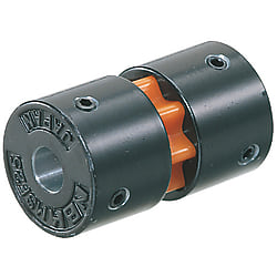
Sleeved Couplings - Sleeved Set Screw
Click this image to zoom it.
Move the mouse over the image to zoom
The torque is conveyed by the serrations engagement on the sleeve. A flexible coupling with a simple structure.
Part Number
Configured Part Number is shown.
Part Number
CAD Data download and 3D preview are not available because the part number has not yet been determined.
- *In order to open the CAD Data download and 3D preview screen, the part number must be fixed.
- Please confirm the part number from "Specification / Dimension"on the left side, and then perform the CAD Data Download / 3D Preview operation.
| Part Number |
|---|
| CPF16-[3,4,5,6,6.35,8]-[3,4,5,6,6.35,8] |
| CPF16-[3,4,5,6,6.35,8]-RDC[3-8/0.1] |
| CPF16-[3,4,5,6,6.35,8]-* |
| CPF16-LDC[3-8/0.1]-[3,4,5,6,6.35,8] |
| CPF16-LDC[3-8/0.1]-RDC[3-8/0.1] |
| CPF16-LDC[3-8/0.1]-* |
| CPF16-*-[3,4,5,6,6.35,8] |
| CPF16-*-RDC[3-8/0.1] |
| CPF16-*-* |
| CPF20-[5,6,6.35,8,10]-[5,6,6.35,8,10] |
| CPF20-[5,6,6.35,8,10]-RDC[5-10/0.1] |
| CPF20-LDC[5-10/0.1]-[5,6,6.35,8,10] |
| CPF20-LDC[5-10/0.1]-RDC[5-10/0.1] |
| CPF25-[6,6.35,8,10,12]-[6,6.35,8,10,12] |
| CPF25-[6,6.35,8,10,12]-RDC[6-11.9/0.1] |
| CPF25-LDC[6-11.9/0.1]-[6,6.35,8,10,12] |
| CPF25-LDC[6-11.9/0.1]-RDC[6-11.9/0.1] |
| CPF32-[8,10,12,14]-[8,10,12,14] |
| CPF32-[8,10,12,14]-RDC[8-14/0.1] |
| CPF32-LDC[8-14/0.1]-[8,10,12,14] |
| CPF32-LDC[8-14/0.1]-RDC[8-14/0.1] |
| Part Number | Standard Unit Price | Minimum order quantity | Volume Discount | Days to Ship | RoHS | Shaft Bore Dia. 1 d1 (or d) (Ø) | Shaft Bore Dia. 2 d2 (or d) (Ø) | O.D. (Ø) | Overall Length (mm) | Allowable Torque Range (N•m) | Allowable Torque (N•m) | Max. Rotational Speed (r/min) | Moment of Inertia (kg・m2) | Options | Shaft I.D. d1 Change Hole Dia. [LDC] Specified in 0.1mm Increment | Shaft I.D. d2 Change Hole Dia. [RDC] Specified in 0.1mm Increment |
|---|---|---|---|---|---|---|---|---|---|---|---|---|---|---|---|---|
- | 1 Piece(s) | 6 Day(s) or more | 10 | 3 ~ 8 | 3 ~ 8 | 16 | 27 | 0.05~1.00 | 0.5 | 39000 | 9 x 10⁻⁷ | - | - | - | ||
- | 1 Piece(s) | 6 Day(s) or more | 10 | 3 ~ 8 | - | 16 | 27 | 0.05~1.00 | 0.5 | 39000 | 9 x 10⁻⁷ | - | - | 3 ~ 8 | ||
- | 1 Piece(s) | 6 Day(s) or more | 10 | 3 ~ 8 | - | 16 | 27 | 0.05~1.00 | 0.5 | 39000 | 9 x 10⁻⁷ | 1 | - | - | ||
- | 1 Piece(s) | 6 Day(s) or more | 10 | - | 3 ~ 8 | 16 | 27 | 0.05~1.00 | 0.5 | 39000 | 9 x 10⁻⁷ | - | 3 ~ 8 | - | ||
- | 1 Piece(s) | 6 Day(s) or more | 10 | - | - | 16 | 27 | 0.05~1.00 | 0.5 | 39000 | 9 x 10⁻⁷ | - | 3 ~ 8 | 3 ~ 8 | ||
- | 1 Piece(s) | 6 Day(s) or more | 10 | - | - | 16 | 27 | 0.05~1.00 | 0.5 | 39000 | 9 x 10⁻⁷ | 1 | 3 ~ 8 | - | ||
- | 1 Piece(s) | 6 Day(s) or more | 10 | - | 3 ~ 8 | 16 | 27 | 0.05~1.00 | 0.5 | 39000 | 9 x 10⁻⁷ | 1 | - | - | ||
- | 1 Piece(s) | 6 Day(s) or more | 10 | - | - | 16 | 27 | 0.05~1.00 | 0.5 | 39000 | 9 x 10⁻⁷ | 1 | - | 3 ~ 8 | ||
- | 1 Piece(s) | 6 Day(s) or more | 10 | - | - | 16 | 27 | 0.05~1.00 | 0.5 | 39000 | 9 x 10⁻⁷ | 1 | - | - | ||
- | 1 Piece(s) | 6 Day(s) or more | 10 | 5 ~ 10 | 5 ~ 10 | 20 | 34 | 0.05~1.00 | 1 | 31000 | 2.7 x 10⁻⁶ | - | - | - | ||
- | 1 Piece(s) | 6 Day(s) or more | 10 | 5 ~ 10 | - | 20 | 34 | 0.05~1.00 | 1 | 31000 | 2.7 x 10⁻⁶ | - | - | 5 ~ 10 | ||
- | 1 Piece(s) | 6 Day(s) or more | 10 | - | 5 ~ 10 | 20 | 34 | 0.05~1.00 | 1 | 31000 | 2.7 x 10⁻⁶ | - | 5 ~ 10 | - | ||
- | 1 Piece(s) | 6 Day(s) or more | 10 | - | - | 20 | 34 | 0.05~1.00 | 1 | 31000 | 2.7 x 10⁻⁶ | - | 5 ~ 10 | 5 ~ 10 | ||
- | 1 Piece(s) | 6 Day(s) or more | 10 | 6 ~ 12 | 6 ~ 12 | 25 | 41 | 1.01~3.00 | 1.5 | 25000 | 8.1 x 10⁻⁶ | - | - | - | ||
- | 1 Piece(s) | 6 Day(s) or more | 10 | 6 ~ 12 | - | 25 | 41 | 1.01~3.00 | 1.5 | 25000 | 8.1 x 10⁻⁶ | - | - | 6 ~ 11.9 | ||
- | 1 Piece(s) | 6 Day(s) or more | 10 | - | 6 ~ 12 | 25 | 41 | 1.01~3.00 | 1.5 | 25000 | 8.1 x 10⁻⁶ | - | 6 ~ 11.9 | - | ||
- | 1 Piece(s) | 6 Day(s) or more | 10 | - | - | 25 | 41 | 1.01~3.00 | 1.5 | 25000 | 8.1 x 10⁻⁶ | - | 6 ~ 11.9 | 6 ~ 11.9 | ||
- | 1 Piece(s) | 6 Day(s) or more | 10 | 8 ~ 14 | 8 ~ 14 | 32 | 48 | 1.01~3.00 | 3 | 19000 | 2.5 x 10⁻⁵ | - | - | - | ||
- | 1 Piece(s) | 6 Day(s) or more | 10 | 8 ~ 14 | - | 32 | 48 | 1.01~3.00 | 3 | 19000 | 2.5 x 10⁻⁵ | - | - | 8 ~ 14 | ||
- | 1 Piece(s) | 6 Day(s) or more | 10 | - | 8 ~ 14 | 32 | 48 | 1.01~3.00 | 3 | 19000 | 2.5 x 10⁻⁵ | - | 8 ~ 14 | - | ||
- | 1 Piece(s) | 6 Day(s) or more | 10 | - | - | 32 | 48 | 1.01~3.00 | 3 | 19000 | 2.5 x 10⁻⁵ | - | 8 ~ 14 | 8 ~ 14 |
Loading...
Basic Information
| Series Name | Oldham | Application | Standard | Features | Low Moment of Inertia |
|---|---|---|---|---|---|
| Allowable Misalignment | Angular Misalignment / Eccentricity | Max. Rotational Speed Range(r/min) | 10001~78000 | Body Material | Alloy |
| Allowable Angular Misalignment(deg) | 2 | Allowable Lateral Misalignment(mm) | 0.2 | Product Category | Coupling Main Body |
| Allowable Lateral Misalignment Range(mm) | 0.02~0.2 | Operating Temperature(°C) | -20::60 |
Specification/Dimensions
-
Shaft Bore Dia. 1 d1 (or d)(Ø)
-
Shaft Bore Dia. 2 d2 (or d)(Ø)
-
O.D.(Ø)
-
Overall Length(mm)
-
Allowable Torque Range(N•m)
-
Allowable Torque(N•m)
-
Max. Rotational Speed(r/min)
-
Options
- 1
-
Shaft I.D. d1 Change Hole Dia. [LDC] Specified in 0.1mm Increment
-
Shaft I.D. d2 Change Hole Dia. [RDC] Specified in 0.1mm Increment
-
type
- CPF
-
CAD
- 2D
- 3D
Days to Ship
-
- All
- 6 Day(s) or Less
Specify Alterations
- The specifications and dimensions of some parts may not be fully covered. For exact details, refer to manufacturer catalogs .
Frequently asked question (FAQ)
- Question: What is the dimensional tolerance of d1 and d2?
- Answer: H8. (before slit machining)
- Question: Is the spacer hollow and can a shaft pass through?
- Answer: The spacer is not hollow, so shafts cannot pass through.
Tech Support
- Factory Automation, Electronics, Tools, & MRO (Maintenance, Repair and Operations)
- Tel:(65) 6733 7211 / FAX:(65) 6733 0211
- 9:00am - 6:00pm (Monday - Friday)
- Technical Inquiry
Payment Method
- Credit Card
- PayPal
- Bank Transfer
Social Media
MISUMI Contact
Copyright © MISUMI Corporation All Rights Reserved.
How can we improve?
How can we improve?