(!)Due to
Microsoft's end of support for Internet Explorer 11 on 15/06/2022, this site does not support the recommended
environment.
Instead, please kindly use other browsers like Google Chrome, Microsoft Edge or Mozilla
Firefox.
- Website Upgrade Completed! System improvements are now LIVE to improve your Ordering experience. You may be logged out after the website update, please log in again.
Pressed Punch Strength Calculation
Problems such as punch edge breakage or damage to the flange section, etc., may occur during
punching processing.
The cause of these problems are often due to insufficient technical data for standard parts or
incorrect selection of punching tool materials and shapes. These indicate appropriate standards
for the use of punch that take into account tool steel fatigue strength and stress
concentration, etc., in the flange in order to reduce such problems.
1. Calculation of punching force
Punching force P [kgf]

2. Damage to punch edge
Stress applied to punch edge σ[kgf/mm2]

[Example 2] Shoulder punch SPAS6-50-P2.8
Jector punch SJAS6-50-P2.8
The possibility of damage to the punch edge when using the above punch (d1 dimension is 0.7 from
 ) is determined.
(Punching conditions are the same as Example 1.)
) is determined.
(Punching conditions are the same as Example 1.)
(a) From formula (2) in case of shoulder punch
σs=4×1.2×64/2.8=110kgf/mm2
(b) From formula (3) in case of jector punch
σJ=4×2.8×1.2×64/(2.82-0.72)
=117kgf/mm2
This calculation method is also applied to the Jector punch, but since the cross-sectional area is small it can get damaged after about 5,000 times.
If stress σ that is less than the allowable stress of each punch material is applied to the punch, it will not break.
(Please consider the above as a guide as it can change depending on conditions, such as mold accuracy, mold structure, processed material dispersion, punch surface coarseness, and heat treatment.)
[Fig. 2] Tool Steel Fatigue Characteristics

[Table 1] Shear Resistance and Tensile Strength of Various Materials
| Material |
Shear resistance τ (kgf/mm2) |
Tensile strength σB (kgf/mm2) |
||
|---|---|---|---|---|
| Softness | Hardness | Softness | Hardness | |
|
Lead Tin Aluminum Duralumin Zinc |
2~ 3 3~ 4 7~11 22 12 |
- - 13~16 38 20 |
2.5~4 4~ 5 8~12 26 15 |
- - 17~22 48 25 |
|
Copper Brass Bronze Nickel silver Silver |
18~22 22~30 32~40 28~36 19 |
25~30 35~40 40~60 45~56 - |
22~28 28~35 40~50 35~45 26 |
30~40 40~60 50~75 55~70 - |
|
Hot rolled steel plate (SPH1 to 8) Cold rolled steel plate (SPC1 to 3) Deep drawing steel plate Structural steel plate (SS330) Structural steel plate (SS400) |
26 or greater 26 or greater 30~35 27~36 33~42 |
28 or greater 28 or greater 28~32 33~44 41~52 |
||
| Steel 0.1%C 〃 0.2%C 〃 0.3%C 〃 0.4%C 〃 0.6%C |
25 32 36 45 56 |
32 40 48 56 72 |
32 40 45 56 72 |
40 50 60 72 90 |
|
Steel 0.8%C 〃 1.0%C Silicon steel plate Stainless steel plate Nickel |
72 80 45 52 25 |
90 105 56 56 - |
90 100 55 66~70 44~50 |
110 130 65 - 57~63 |
|
Leather Mica 0.5 mm thickness Mica 2 mm thickness Fiber Birch |
0.6~0.8 8 5 9~18 2 |
- - - - - |
||
*{N}=kgf×9.80665
(Schuler Pressen GmbH, Bliss Manufacturing Co., Ltd.)
3. Minimum pressed diameter
Minimum press diameter dmin

[Fig. 3] Press Processing Limit

4. Damage due to buckling
Buckling load P [kgf]

In order to improve buckling strength P from this Euler’s formula, it is better to use a
stripper guide, use materials with a large vertical elasticity coefficient (SKD→SKH→HAP), and
shorten the length of the cutting edge.
The buckling load P represents the value when the punch buckles and breaks. When selecting a
punch, a safety factor of 3 to 5 must be considered.
When punching small holes, there is a need to choose a punch with particular attention to
buckling load and the stress to be applied to the punch.
[Example 4] Calculate a total length that does not buckle when a hole of ø8 is punched through
stainless steel SUS304 (plate thickness 1 mm, tensile strength σb = 60
kgf/mm2).
with a straight punch (SKD11).
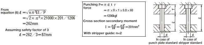
If the punch plate thickness T is 20 mm, buckling can be prevented by using a punch with a total length of 107 mm or less. Total length should be 87 mm or less in case of stripper standard (punch plate guides the blade edge between gaps) punch.

5. Damage to flange
Flange damage is caused by tensile force (tensile force equivalent to punching load is applied to the punch at breakthrough) and stress concentration due to elastic wave generated during pressing.
For flange damage prevention, there are measures such as follows;
- 1. Increase R under flange to mitigate stress concentration. (Use of punch for pressing thick plates)
-
2.
Make the flange stronger than the punch edge.
However, here, the optimum shank diameter that doesn’t damage the flange is obtained by method 2.
Calculation method
P=πdtτ
The flange allowable stress σw:
(a) In case of shoulder punch
σw=Pα/At
=4Pα/πD2
(b) In case of jector punch
σwJ=4Pα/π(D2-M2)
Find the flange strength when punching conditions
are the same as Example 1.
(a) In case of shoulder punch
At=πD2/4
(b) In case of jector punch
At=π(D2-M2)/4
D: Shank diameter
Α: Stress concentration coefficient
(a) In case of shoulder punch α≒3
Punch for pressing thick plates α≒2
Taper head punch α≒1.6
(b) In case of Jector punch α≒5
[Fig. 5] Damage to Flange

How to Find from Figure


[Fig. 6]
a) Find intersection point “a” between plate thickness “t” and shear resistance “τ”.
b) Move the intersection point “a” to the left or right, and find intersection point “b” with
punch edge diameter.
- As intersection point “b” is below the line of 10^5 times of pressing, both SKH and SKD can withstand more than 10^5 times of pressing.


[Fig. 7]
c) Move the intersection point “a” to the right, and find intersection point “c” with punch edge
diameter.
d) Drop down the intersection point “c” to find intersection points “d” and “d'” with a line
(for standard and thick plates) of 10^4 times of pressing.
e) From the extension line of the intersection points “d” and “d'” to the right, find the shank
diameter.
- For standard punch (SKH), as the right-hand scale shows 14.0, select a shank diameter of ø16.
- For thick plate punch (SKH), as the right-hand scale shows 11.8, select a shank diameter of ø13.
This selection table has been created from the results of fatigue tests for tension and compression. As values may differ slightly from actual punching, please only use this as a guide.

PDF list
Payment Method
- Credit Card
- PayPal
- Bank Transfer



Social Media
MISUMI Contact
Copyright © MISUMI Corporation All Rights Reserved.