(!)Due to Microsoft's end of support for Internet Explorer 11 on 15/06/2022, this site does not support the recommended environment.
Instead, please kindly use other browsers like Google Chrome, Microsoft Edge or Mozilla Firefox.
50,000 Stock items for Same Day Ship Out.
All Categories
Categories
- Automation Components
A wide variety of standard and configurable components for factory automation engineers in industries such as automotive, semiconductor, packaging, medical and many more.
- Linear Motion
- Rotary Motion
- Connecting Parts
- Rotary Power Transmission
- Motors
- Conveyors & Material Handling
- Locating, Positioning, Jigs & Fixtures
- Inspection
- Sensors, Switches
- Pneumatics, Hydraulics
- Vacuum Components
- Hydraulic Equipment
- Discharging / Painting Devices
- Pipe, Tubes, Hoses & Fittings
- Modules, Units
- Heaters, Temperature Control
- Framing & Support
- Casters, Leveling Mounts, Posts
- Doors, Cabinet Hardware
- Springs, Shock Absorbers
- Adjusting, Fastening, Magnets
- Antivibration, Soundproofing Materials, Safety Products
- Fasteners
A good selection of accessories such as screws, bolts, washers and nuts that you may need for your daily engineering usage.
- Materials
Browse industrial materials ranging from heat insulating plates, sponges, to metal and plastic materials in different sizes to meet your various applications.
- Wiring Components
A wide variety of wiring parts for connecting and protecting control and PC parts including Connectors, Cables, Electric Wires, Crimping Terminals and more.
- LAN Cables / Industrial Network Cables
- Cables by Application
- Cables with Connectors
- RS232 / Personal Computers / AV Cables
- Wires/Cables
- Connectors (General Purpose)
- Crimp Terminals
- Zip Ties
- Cable Glands
- Cable Bushings/Clips/Stickers
- Screws/Spacers
- Cable Accessories
- Tubes
- Protection Tubes
- Ducts/Wiremolds
- General Purpose Tools
- Dedicated Tools
- Soldering Supplies
- Electrical & Controls
A wide variety of controls and PC parts for electrical engineers including Controls, Powers, PC parts and more.
- Cutting Tools
A wide variety of cutting tools for many uses and work materials including End Mills, Drills, Cutters, Reamers, Turning Tools and more.
- Carbide End Mills
- HSS End Mills
- Milling Cutter Inserts/Holders
- Customized Straight Blade End Mills
- Dedicated Cutters
- Turning Tools
- Drill Bits
- Screw-Hole-Related Tools
- Reamers
- Chamfering / Centering Tools
- Fixtures Related to Cutting Tools
- Step Drills
- Hole Saws
- Clean Key Cutters
- Core Drills (Tip Tools)
- Magnetic Drilling Machine Cutters
- Drill Bits for Electric Drilling Machines
- Woodworking Drill Cutters
- Drills for Concrete
- Processing Tools
A wide variety of tools and supplies used in processing including Machine Tools, Measurement Tools, Grinding and Polishing Supplies and more.
- Material Handling & Storage
A wide variety of goods used in shipment, material handling and warehouse including Tape supplies, Stretch film, Truck, Shelf, Crane and more.
- Tape Supplies
- Cushioning Materials
- Stretch Films
- Cardboard
- Plastic Bags
- PP Bands
- Magic Tapes / Tying Belts
- Rubber Bands
- Strings/Ropes
- Cable Ties
- Tags
- Labelers
- Unpacking Cutters
- Packing Support Equipment
- Cloth Sheets for Packing
- Conveyance/Dolly Carts
- Tool Wagons
- Tool Cabinets / Container Racks
- Lifters / Hand Pallets
- Container Pallets
- Storage Supplies
- Shelves/Racks
- Work Benches
- Suspended Clamps/Suspended Belts
- Jack Winches
- Chain Block Cranes
- Bottles/Containers
- Bicycle Storage Area
- Safety & General Supplies
A large variety of goods for every kind of factories and offices including Protection items, Cleaning supplies, sanitations, office supplies and more.
- Lab & Clean Room Supplies
A large variety of items used in R&D and Clean Room including research Equipment, Laboratory Essentials, Analysis Supplies, Clean Environment-Related Equipment and more.
- Press Die Components
Choose from thousands of standard stamping die components including Punch & Die, Gas Springs, Guide Components, Coil Springs and many more.
- Plastic Mold Components
Browse our wide variety of mold components including Ejector Pins, Sleeves, Leader Components, Sprue Bushings and many more.
- Ejector Pins
- Sleeves, Center Pins
- Core Pins
- Sprue bushings, Gates, and other components
- Date Mark Inserts, Recycle Mark Inserts, Pins with Gas Vent
- Undercut, Plates
- Leader Components, Components for Ejector Space
- Mold Opening Controllers
- Cooling or Heating Components
- Accessories, Others
- Components of Large Mold, Die Casting
- Injection Molding Components
Browse our injection molding components including Heating Items, Couplers, Hoses and more.
- Injection Molding Machine Products
- Accessories of Equipment
- Auxiliary Equipment
- Air Nippers
- Air Cylinders
- Air Chuck for Runner
- Chuck Board Components
- Frames
- Suction Components
- Parallel Air Chuck
- Special Air Chuck
- Chemical for Injection Molding
- Mold Maintenance
- Heating Items
- Heat Insulation Sheets
- Couplers, Plugs, One-touch Joints
- Tubes, Hoses, Peripheral Components
Search by Application
Brands


- Please Note our New Address (effective April 1, 2024): 331 North Bridge Rd, #05-01 Odeon 331, Singapore 188720.
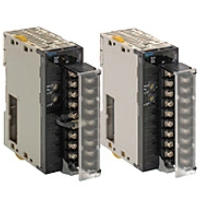
CJ series process input/output unit
Part Number
Configured Part Number is shown.
CJ1W-AD04U
Process I/O Unit Specifications
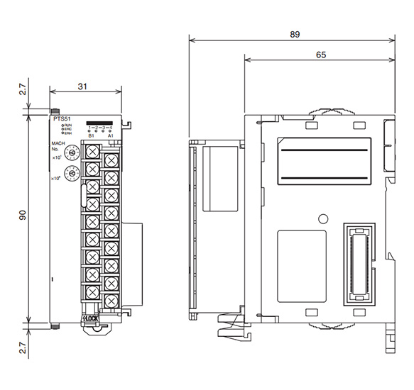
CJ1W-AD04U outline drawing
Specifications
- Signal range: full multi input: Pt 100, JPt 100, Pt 1000, K, J, T, L, R, S, B, 4 to 20 mA, 0 to 20 mA, 1 to 5 V, 0 to 5 V, 0 to 10 V
- Conversion speed: 250 ms / 4 points
- Accuracy (at ambient temperature of 25°C)
Accuracy: platinum resistance thermometer input: (the larger of ±0.3 of PV or ±0.8°C ) ±1 digit or less
Thermocouple input: (Larger of ±0.3% of PV) ±1 digit or less *1
Voltage/current input: (±0.3% of F.S.) ±1 digit or less - Current consumption: 0.32 A (5V Series)
*1. L and −100°C or less for K and T are ±2°C ±1 digit max. 200°C or less for R and S is ±3°C±1 digit max. B less than 400°C is not covered by the warranty.
Specifications
| Item | Specifications |
|---|---|
| Unit Group | CJ Series High Function I/O Unit |
| External Dimensions (mm) | 31 (W) × 90 (H) × 65 (D) |
| Weight | 150 g or less |
| External Connection Terminals | 18-Point removable terminal block (M3 screws, correct tightening torque of 0.5 N·m) |
| Unit No. of Setting Switches | 00 to 95 |
| Self-Diagnostic Function | Diagnostic results displayed via the LEDs |
| Mountable Position | CPU equipment or CJ series expansion devices |
| Number of Installable Units | 40 (Installation of 10 units × 4 racks) The total current consumption for all units (including CPU unit, etc.) equipped for each (CPU unit or expansion device) must be less than the maximum supplied power for the power supply unit |
| Ambient Operating Temperature | 0 to 55°C |
| Ambient Operating Humidity | 10 to 90% RH (assuming no condensation) |
| Item | Specifications | |
|---|---|---|
| Format | Model CJ1W-AD04U | |
| Applicable Controllers | CJ/NJ Series | |
| Unit Types | CJ Series high-functioning I/O unit | |
| Mountable Position | CPU unit, expansion device | |
| Number of Installable Units | 40 units (must be within current consumption and power consumption range) | |
| Number Of Configurable Units | 00 to 95 (No duplicating for high-functioning I/O units) | |
| Data Exchange Area With CPU Unit | High-Functioning I/O Unit CIO Area (Operation Data) | 10 CH/Unit |
| This unit → CPU unit: all process values, process value alarms (L, H), conversion data enabled flags, input error, cold junction sensor errors | ||
| High-Functioning I/O Unit Allocated DM Area (Setting Parameters) | 100 words/unit | |
| CPU unit → this unit: input types, scaling maximum/minimum values, process value alarm settings values (L, H), zero span adjustment value, warning on delay time, warning hysteresis, memory area settings allocated for expansion | ||
| Memory Area Allocated for Expansion (Expansion Settings Parameters) | 1 CH/unit | |
| CPU unit → this unit: process value alarm output | ||
| Inputs | 4 | |
| Input Type | Platinum Resistance Thermometer: Pt100 (JIS, IEC), Pt1000, JPt100 Thermocouple: K, J, T, L, R, S, B Current: 4 to 20 mA, 0 to 20 mA Voltage: 1 to 5 V, 0 to 5 V, 0 to 10 V The input type can be set individually for each input | |
| Scaling (Voltage/Current Input) | Voltage and current input data to be stored in the allocated words in the CIO area must be scaled (with the minimum and maximum values set by user) (4 points set separately) | |
| Data Storage in the CIO Area | Voltage/Current Input: The value derived from carrying out the following processing in order of the actual process data in the input range is stored in four digits hexadecimal (binary values) in the allocated words in the CIO Area. 1) Scaling →2) Zero/span adjustment → 3) Output limits Temperature input: The value derived from carrying out the following processing in order of the actual process data in the input range is stored in four digits hexadecimal (binary values) in the allocated words in the CIO Area. 1) ⁰C, °F conversion → 2) Zero/span adjustment → 3) Output limits (temperatures are typically stored at 10 times the value) | |
| Accuracy (25°C) (Sensor Error not Included) | Platinum Resistance Thermometer input: (Larger of specified value ±0.3% or ±0.8°C) ±1 digit max. | |
| Thermocouple input: (Larger of specified value ±0.3% or ±1.5°C) ±1 digit or less However L: ±2°C ±1 digit max. −100°C or less for K and T: ±2°C ±1 digit max. 200°C or less for R and S: ±3°C ±1 digit max. 400°C for B or less not specified | ||
| Voltage/current input: (±0.3% F.S.) ±1 digit max. | ||
| Temperature Coefficient | ±100 ppm F.S./°C max. | |
| Resolution | 1/12,000 (with voltage/current input) See catalog section "Input Types and Input Ranges" for temperature inputs | |
| Input Signal Range | Voltage/current input: -5% to 105% of the input range set in scaling Temperature input: ±20°C or ±20°F relative to upper and lower limits for each sensor range | |
| Maximum Rated Input | Voltage input: ±15 V, Current input: 30 mA | |
| Input Impedance | Temperature input: 10 kΩ min., Voltage input: 1 MΩ min., Current input: 250 Ω (fixed) | |
| Warmup Time | 30 mins. | |
| Thermocouple Input | Uses internal sensors for cold junction compensation | |
| Platinum Resistance Thermometer Input | · Measurement method: 3 wire method · Allowable conductor resistance: 20 Ω max. per wire · Input detection current: 1.1 mA | |
| Conversion Period | 250 ms/4 inputs | |
| Maximum Time to Store Data in CPU Unit | Conversion period + one CPU unit cycle | |
| Disconnection Detection | Disconnections can be detected at each input (excluding voltage/current input of 0 to 20 mA, 0 to 5 V, and 0 to 10 V) Detection level · Temperature input: When exceeding 20°C or 20°F relative to the upper and lower limits for each sensor range · +1 to +5 V: input signal < 0.3 V · 4 to 20 mA: input signal < 1.2 mA For connection interruptions or when out of input range, the disconnection detection flag is switched ON The process value overrange direction for when a disconnection occurs can be specified | |
| Process Value Alarm | The process value 2-point alarm (L, H), hysteresis and on delay timer (0 to 60 s) can be set The process value alarm bit can be copied to a address in the available memory area allocated for memory | |
| Insulation | Between input and controller signal: power supply = transformer, signal = photo coupler Between all inputs: power supply = transformer, signal = photo coupler | |
| Insulation Resistance | Between mutual batch channels: 20 MΩ (with 500 V DC ohmmeter) | |
| Dielectric Strength | Between mutual batch channels: 500 V AC, 50/60 Hz for 1 minute, Leakage current 1 mA max. | |
| External Connection | Terminal block (removable) | |
| Display | Front: LED × 3 (for normal operation, errors detected by unit, errors detected by CPU unit) | |
| Setting Part | Front rotary switch: Unit number (0 to 95) | |
| Current Consumption (Supplied by Power Supply Unit) | 5 V DC, 320 mA max. | |
| External Dimensions (mm) | 31 (W) × 90 (H) × 65 (D) | |
| Weight | 150 g or less | |
*1. Square root calculation function is possible only during DC input. The square root is not extracted for temperature input. The square root calculation function is only available when the maximum scaling value is greater than the minimum scaling value. The square root is not extracted when the maximum scaling value is less than the minimum scaling value. When the square root function is used, set the scaling values after square root calculation (e.g., for flow rates or other values) for the process value scaling A and B settings.
*2. The cold junction compensation method specification function is available only for thermocouple inputs.
*3. The resistance thermometer input compensation function is only available for the resistance thermometer input.
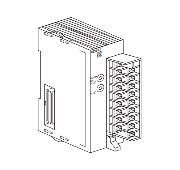
Outline drawing
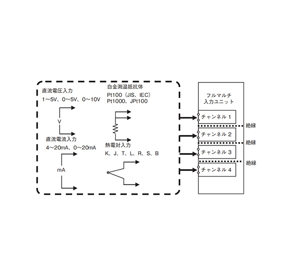
System configuration
| Part Number |
|---|
| CJ1W-AD04U |
| Part Number | Standard Unit Price | Minimum order quantity | Volume Discount | Days to Ship |
|---|---|---|---|---|
SGD 1,027.29 | 1 Piece(s) | 4 Day(s) or more |
Loading...
Basic Information
| Type | Input | Input Type | Voltage / Current / Thermocouple / Temperature Measuring Resistor | Number of Input Channels | 4 |
|---|---|---|---|---|---|
| Input Range | Other | A/D Conversion Speed (Conversion Time) | Less than 100 to 500 ms | Terminal shape | Terminal Block |
| Representative Standard | CE / UL / CUL / CSA | Consumed current (5 V system)(A) | 0.32 | Input Signal Range | Pt 100, JPt 100, Pt 1000, K, J, T, L, R, S, B, 4 to 20 mA, 0 to 20 mA, 1 to 5 V, 0 to 5 V, 0 to 10 V |
- The specifications and dimensions of some parts may not be fully covered. For exact details, refer to manufacturer catalogs .
Tech Support
- Factory Automation, Electronics, Tools, & MRO (Maintenance, Repair and Operations)
- Tel:(65) 6733 7211 / FAX:(65) 6733 0211
- 9:00am - 6:00pm (Monday - Friday)
- Technical Inquiry
Payment Method
- Credit Card
- PayPal
- Bank Transfer
Social Media
MISUMI Contact
Copyright © MISUMI Corporation All Rights Reserved.
How can we improve?
How can we improve?