(!)Due to Microsoft's end of support for Internet Explorer 11 on 15/06/2022, this site does not support the recommended environment.
Instead, please kindly use other browsers like Google Chrome, Microsoft Edge or Mozilla Firefox.
50,000 Stock items for Same Day Ship Out.
All Categories
Categories
- Automation Components
A wide variety of standard and configurable components for factory automation engineers in industries such as automotive, semiconductor, packaging, medical and many more.
- Linear Motion
- Rotary Motion
- Connecting Parts
- Rotary Power Transmission
- Motors
- Conveyors & Material Handling
- Locating, Positioning, Jigs & Fixtures
- Inspection
- Sensors, Switches
- Pneumatics, Hydraulics
- Vacuum Components
- Hydraulic Equipment
- Discharging / Painting Devices
- Pipe, Tubes, Hoses & Fittings
- Modules, Units
- Heaters, Temperature Control
- Framing & Support
- Casters, Leveling Mounts, Posts
- Doors, Cabinet Hardware
- Springs, Shock Absorbers
- Adjusting, Fastening, Magnets
- Antivibration, Soundproofing Materials, Safety Products
- Fasteners
A good selection of accessories such as screws, bolts, washers and nuts that you may need for your daily engineering usage.
- Materials
Browse industrial materials ranging from heat insulating plates, sponges, to metal and plastic materials in different sizes to meet your various applications.
- Wiring Components
A wide variety of wiring parts for connecting and protecting control and PC parts including Connectors, Cables, Electric Wires, Crimping Terminals and more.
- LAN Cables / Industrial Network Cables
- Cables by Application
- Cables with Connectors
- RS232 / Personal Computers / AV Cables
- Wires/Cables
- Connectors (General Purpose)
- Crimp Terminals
- Zip Ties
- Cable Glands
- Cable Bushings/Clips/Stickers
- Screws/Spacers
- Cable Accessories
- Tubes
- Protection Tubes
- Ducts/Wiremolds
- General Purpose Tools
- Dedicated Tools
- Soldering Supplies
- Electrical & Controls
A wide variety of controls and PC parts for electrical engineers including Controls, Powers, PC parts and more.
- Cutting Tools
A wide variety of cutting tools for many uses and work materials including End Mills, Drills, Cutters, Reamers, Turning Tools and more.
- Carbide End Mills
- HSS End Mills
- Milling Cutter Inserts/Holders
- Customized Straight Blade End Mills
- Dedicated Cutters
- Turning Tools
- Drill Bits
- Screw-Hole-Related Tools
- Reamers
- Chamfering / Centering Tools
- Fixtures Related to Cutting Tools
- Step Drills
- Hole Saws
- Clean Key Cutters
- Core Drills (Tip Tools)
- Magnetic Drilling Machine Cutters
- Drill Bits for Electric Drilling Machines
- Woodworking Drill Cutters
- Drills for Concrete
- Processing Tools
A wide variety of tools and supplies used in processing including Machine Tools, Measurement Tools, Grinding and Polishing Supplies and more.
- Material Handling & Storage
A wide variety of goods used in shipment, material handling and warehouse including Tape supplies, Stretch film, Truck, Shelf, Crane and more.
- Tape Supplies
- Cushioning Materials
- Stretch Films
- Cardboard
- Plastic Bags
- PP Bands
- Magic Tapes / Tying Belts
- Rubber Bands
- Strings/Ropes
- Cable Ties
- Tags
- Labelers
- Unpacking Cutters
- Packing Support Equipment
- Cloth Sheets for Packing
- Conveyance/Dolly Carts
- Tool Wagons
- Tool Cabinets / Container Racks
- Lifters / Hand Pallets
- Container Pallets
- Storage Supplies
- Shelves/Racks
- Work Benches
- Suspended Clamps/Suspended Belts
- Jack Winches
- Chain Block Cranes
- Bottles/Containers
- Bicycle Storage Area
- Safety & General Supplies
A large variety of goods for every kind of factories and offices including Protection items, Cleaning supplies, sanitations, office supplies and more.
- Lab & Clean Room Supplies
A large variety of items used in R&D and Clean Room including research Equipment, Laboratory Essentials, Analysis Supplies, Clean Environment-Related Equipment and more.
- Press Die Components
Choose from thousands of standard stamping die components including Punch & Die, Gas Springs, Guide Components, Coil Springs and many more.
- Plastic Mold Components
Browse our wide variety of mold components including Ejector Pins, Sleeves, Leader Components, Sprue Bushings and many more.
- Ejector Pins
- Sleeves, Center Pins
- Core Pins
- Sprue bushings, Gates, and other components
- Date Mark Inserts, Recycle Mark Inserts, Pins with Gas Vent
- Undercut, Plates
- Leader Components, Components for Ejector Space
- Mold Opening Controllers
- Cooling or Heating Components
- Accessories, Others
- Components of Large Mold, Die Casting
- Injection Molding Components
Browse our injection molding components including Heating Items, Couplers, Hoses and more.
- Injection Molding Machine Products
- Accessories of Equipment
- Auxiliary Equipment
- Air Nippers
- Air Cylinders
- Air Chuck for Runner
- Chuck Board Components
- Frames
- Suction Components
- Parallel Air Chuck
- Special Air Chuck
- Chemical for Injection Molding
- Mold Maintenance
- Heating Items
- Heat Insulation Sheets
- Couplers, Plugs, One-touch Joints
- Tubes, Hoses, Peripheral Components
Search by Application
Brands


- Scheduled Maintenance Notice: This site will be unavailable due to scheduled maintenance from 9:00 21/4/2024 to 6:00 (SGT) 22/4/2024. We apologize for the inconvenience.
- Please Note our New Address (effective April 1, 2024): 331 North Bridge Rd, #05-01 Odeon 331, Singapore 188720.
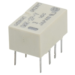
Surface-mount Relay - G6K
[Features]
· A surface mounted relay that achieves the smallest mounting surface area in its class and a low profile.
· An ultra small type with a height of 5.2 mm, a width of 6.5 mm, and a length of 10 mm. Can be used for high-density mounting (G6k (U)-2F (-Y) type).
· A low profile type with a height of just 5.2 mm, promising improved mounting efficiency (G6k (U)-2F (-Y) type).
· Ultra-light with a weight of just (approx.) 0.7 g for faster mounting speeds.
· Approximately 70% lower power consumption compared to the manufacturer's other products. Achieves a high sensitivity at 100mW.
· Its unique terminal structure with a high infrared radiating efficiency makes it easier to increase the temperature of the terminal during IRS mounting, providing good soldering properties (surface mounted terminal type).
· Features a high withstand voltage between coil-contacts of AC1,500V. Also features impulse withstand voltage of 1.5kV10 × 160 μs (FCCPart68 compliant).
· Y-series product lines also available. Features an optimized distance between the coil contacts and terminals. Also features an impulse withstand voltage of 2.5kV2 × 10 μs (Telcordia standard compatible).
· The standard type is UL and CSA standard compliant. EN60950-certified.
Japanese Only
Part Number
Configured Part Number is shown.
PCB Terminal Standard Model Types
| Structure | Type | Contact Configuration | Model | Coil Rated Voltage (V) |
|---|---|---|---|---|
| Plastic Seal Type | Single Stable Type | 2c | Model G6K-2P | 4.5 DC |
| 5 DC | ||||
| 12 DC | ||||
| 24 DC | ||||
| Model G6K-2P-Y (Highly Insulated) | 3 DC | |||
| 4.5 DC | ||||
| 5 DC | ||||
| 12 DC | ||||
| 24 DC |
G6K-2P Specifications
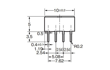
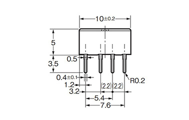
G6K-2P dimensional outline drawing
- The general dimensional tolerance is ±0.3 mm.
- Units: mm
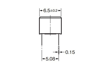
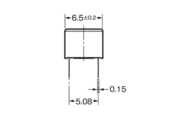
G6K-2P dimensional outline drawing
- The general dimensional tolerance is ±0.3 mm.
- Units: mm
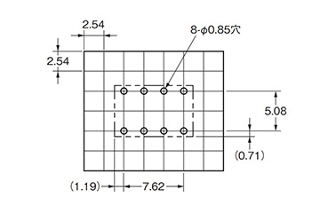
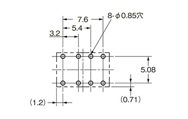
PCB processing dimensions
- The dimensional tolerance is ±0.1 mm.
- Units: mm
G6K-2P-Y Specifications
G6K-2G-Y dimensional outline drawing
- The general dimensional tolerance is ±0.3 mm.
- Units: mm
G6K-2G-Y dimensional outline drawing
- The general dimensional tolerance is ±0.3 mm.
- Units: mm
PCB processing dimensions
- The dimensional tolerance is ±0.1 mm.
- Units: mm
Surface Mount Relay Details
Ratings
| Items | Rated Current (mA) | Coil Resistance (Ω) | Operating Voltage (V) | Release Voltage (V) | Maximum Allowable Voltage (V) | Power Consumption (mW) | |
|---|---|---|---|---|---|---|---|
| Rated Voltage (V) | |||||||
| DC | 3 | 33.0 | 91 | 80% or Less | 10% or More | 150% | Approx. 100 |
| 4.5 | 23.2 | 194 | |||||
| 5 | 21.1 | 237 | |||||
| 12 | 9.1 | 1,315 | |||||
| 24 | 4.6 | 5,220 | |||||
- *1: The rated current and coil resistance are measured at a coil temperature of 23°C and a tolerance of ±10%.
- *2: The operating characteristics are measured at a coil temperature of 23°C.
- *3: The maximum allowable voltage is the maximum voltage that can be applied to a relay coil.
Switching Part (Contact Part)
| Load | Resistance Load |
|---|---|
| Rated Load | 125 V AC 0.3 A 30 V DC 1 A |
| Rated Conduction Current | 2 A |
| Maximum Contact Voltage Value | 125 V AC 60 V DC |
| Maximum Contact Current Value | 1 A |
Performance
| Type | Single Stable Type | ||
|---|---|---|---|
| Model G6K-2P | Model G6K-2P-Y | ||
| Contact Resistance *1 | 100 mΩ or Less | ||
| Operation (Set) Time *2 | 3 ms or Less (Approx. 1.4 ms) | ||
| Recovery (Reset) Time *2 | 3 ms or Less (Approx. 1.3 ms) | ||
| Minimum Set/Reset Pulse Width | - | ||
| Insulation Resistance *3 | 1,000 MΩ or More (at 500 V DC) | ||
| Withstand Voltage | Between Coil and Contact | 1,500 V AC 50/60 Hz 1 min | |
| Between Contacts of Different Polarities | 1,000 V AC 50/60 Hz 1 min | ||
| Between Contacts of Same Polarity | 750 V AC 50/60 Hz 1 min | ||
| Impulse Withstand Voltage | Between Coil and Contact | 1,500 V 10 × 160 μs | 2,500 V 2 × 10 μs, 1,500 V 10 × 160 μs |
| Between Contacts of Different Polarities | 1,500 V 10 × 160 μs | ||
| Between Contacts of Same Polarity | |||
| Vibration | Durability | 10 to 55 to 10 Hz, Semi Amplitude 2.5 mm (Double Amplitude 5 mm), 55 to 500 Hz 300 m/s2 | |
| Malfunction | 10 to 55 to 10 Hz, Semi Amplitude 1.65 mm (Double Amplitude 3.3 mm), 55 to 500 Hz 200 m/s2 | ||
| Shock / Impact | Durability | 1,000 m/s2 | |
| Malfunction | 750 m/s2 | ||
| Durability | Mechanical | 50,000,000 Times or More (Switching Frequency: 36,000 Times/h) | |
| Electrical | 100,000 Times or More (Rated Load, Switching Frequency: 1,800 Times/h) | ||
| Failure Rate P Level *4 | DC 10 mV 10 μA | ||
| Ambient Operating Temperature | -40 to +70°C (Assuming No Freezing or Condensation) | ||
| Operating Ambient Humidity | 5 to 85%RH | ||
| Weight | Approx. 0.7 g | ||
- *The above values are the initial default values.
- *1. Measurement Conditions: 1 V DC 10 mA, voltage drop method.
- *2. The values within ( ) are the actual values.
- *3. Measurement conditions: Measuring the same spot for the withstand voltage items using a 500 V DC insulation resistance meter.
- *4. This value is obtained with a switching frequency of 120 times/min. and a contact resistance failure value of 50Ω. These values may vary depending on switching frequency and operating conditions, meaning it is always recommended to double-check under actual load conditions.
Common items
- The temperature of the terminal easily increases during IRS mounting, ensuring good soldering properties (surface mounted terminal type.)
- Features a high withstand voltage between coil contacts of 1,500 V AC. Also features an impulse withstand voltage of 1.5 kV 10 × 160 μs (FCC Part 68 compliant.)
- Y-series product lines also available. Features an optimized distance between the coil contacts and terminals. Also features an impulse withstand voltage of 2.5 kV 2 × 10 μs (Telcordia standard compatible.)
*Refer to the catalog for product information other than that above.
| Part Number |
|---|
| G6K-2P DC5 |
| G6K-2P DC12 |
| G6K-2P DC24 |
| G6K-2P-Y DC3 |
| G6K-2P-Y DC5 |
| G6K-2P-Y DC12 |
| G6K-2P-Y DC24 |
| Part Number | Standard Unit Price | Minimum order quantity | Volume Discount | Days to Ship | Coil rated voltage (DC) (V) | Type |
|---|---|---|---|---|---|---|
SGD 6.20 | 1 Piece(s) | 67 Day(s) | 5 | - | ||
SGD 6.13 | 1 Piece(s) | Same day | 12 | - | ||
SGD 11.38 | 1 Piece(s) | Same day | 24 | - | ||
SGD 9.56 | 1 Piece(s) | Same day | 3 | High insulation | ||
SGD 6.20 | 1 Piece(s) | Same day | 5 | High insulation | ||
SGD 9.56 | 1 Piece(s) | Same day | 12 | High insulation | ||
SGD 8.47 | 1 Piece(s) | Same day | 24 | High insulation |
Loading...
Basic Information
| Application | For Signals | Contact Configuration | 2c | Latch function | NA |
|---|---|---|---|---|---|
| Terminal shape | For Circuit Boards | Contact rated current (minimum value for AC and DC)(A) | 0.3 | Dimension height(mm) | 5 |
| Dimension width(mm) | 10 | Dimension depth(mm) | 6.5 | Classification | Single stable shape |
| Protective Structure | Plastic seal type | Contact mechanism | Crossbar twin | Circuit Board Mounting | Circuit Board Hole Insertion |
| AC rated load(V)/(A) | AC125/0.3 | DC rated load(V)/(A) | DC30/1 |
- The specifications and dimensions of some parts may not be fully covered. For exact details, refer to manufacturer catalogs .
Tech Support
- Factory Automation, Electronics, Tools, & MRO (Maintenance, Repair and Operations)
- Tel:(65) 6733 7211 / FAX:(65) 6733 0211
- 9:00am - 6:00pm (Monday - Friday)
- Technical Inquiry
Payment Method
- Credit Card
- PayPal
- Bank Transfer
Social Media
MISUMI Contact
Copyright © MISUMI Corporation All Rights Reserved.
How can we improve?
How can we improve?